 Fig 1. Why larger apertures are desirable! Simulation of effect of aperture on eyepiece view of M13.
Orwell Astronomical Society (Ipswich)
Millennium Telescope
At the end of the 1990s, members of OASI started work on an ambitious project to design and build a large (circa half metre aperture) Dobsonian telescope. The aim was to provide a first class instrument for use by members of the Society and to mark the onset of the third millennium. Unfortunately, as with many millennial projects, the original timescales were hopelessly optimistic, and first light (with a silvered main mirror) was not achieved until 18 April 2005! This page summarises the progress of the project.
During 1998, experienced members of OASI ran sessions at Orwell Park Observatory grinding a 220 mm mirror, and many members had the opportunity to gain hands-on experience of each stage of the grinding process. Following the success of the project, at a meeting on 22 February 1999, the committee agreed to finance a more ambitious project aimed at designing and building a large Newtonian reflector using the latest materials and techniques. The new telescope was intended to mark the onset of the third millennium and accordingly was christened the Millennium Telescope. Completion of the instrument was anticipated by the end of 2000.
An article in the August 1999 Newsletter announced the project to members of OASI and provided the following specification for the main mirror of the instrument:
| Parameter | Description |
| Material | Pyrex low expansion glass |
| Diameter | 48 cm |
| Thickness | 4 cm |
| Weight | 16 kg |
| Design focal length | 2.12 m (f4.5) |
Grinding the primary mirror was thought likely to be the most onerous piece of work: the rear would be ground flat to facilitate mounting and aligning and the front would be ground to a concave paraboidal shape with a depth of 6.6 mm, involving the removal of 1.5 kg of glass from the blank.
In planning any large telescope, there is always an outbreak of "aperture fever" (a burning desire to have the biggest aperture possible)! Figure 1 illustrates why: it shows computer simulations of the eyepiece view of the well known Messier object, M13 in Hercules, with primary mirror diameters varying from 200 mm to 760 mm. Note the dramatically increased resolution offered by the larger apertures. The size of the primary mirror of the Millennium Telescope was selected as a compromise between size, cost, transportability and the abilities of members to figure the optical surface.
Fig 1. Why larger apertures are desirable! Simulation of effect of aperture on eyepiece view of M13.
During 1999, Mike Harlow led work by many members of OASI to complete initial shaping and rough grinding of the 48 cm main mirror. Figures 2-8 show the early stages of the grinding work.
 Fig 2. Close up of the primary mirror during coarse grinding.
 Fig 3. St. John Robinson.
 Fig 4. Barry Ellam.
 Fig 5. Ted Sampson.
 Fig 6. Kathry Gerry & Ted Samson.
 Fig 7. Martin Cook.
 Fig 8. Mike Whybray.
 Fig 9. Pete Richards.
 Fig 10. Roy Tremlett.
Once initial shaping and rough grinding was complete, Mike undertook fine grinding of the main mirror with 400 grade carborundum and blocked up the 9.5 cm minor axis secondary mirror (illustrated in figure 11 on an earlier project) and undertook fine grinding with 400 grade abrasive.
 Fig 11. The secondary mirror and its polisher.
Mike and co-workers made good progress during early-mid 1999; however, due to organisational difficulties and personal commitments, work tailed off in late 1999 and there was thereafter little progress. By early 2002, the project was effectively moribund.
At a meeting on 27 March 2002, the committee of OASI addressed the question whether to abandon the moribund Millennium Telescope project or to re-energise the work and push it through to completion. At the meeting, Neil Morley agreed to lead a small group to undertake a thorough feasibility study and mechanical design of the instrument with the intent to present a full design proposal together with detailed parts list and cost estimate at a future committee meeting. This would enable the committee to make an informed decision whether to support the project to completion, or to abandon it.
The remaining work on the primary mirror involved final figuring and polishing and Mike Harlow estimated that around 10-15 hours of additional effort was required. Figuring and polishing a large mirror is a slow, tedious and exacting process; there aren't many people with the skills or determination to take on the work and OASI was fortunate indeed that Mike was willing to undertake it. The work would be best achieved over a concentrated period to maintain continuity, and Mike envisaged that it would be possible to complete the mirror during 2003. However, work on the mirror could be carried on independently of work to prepare an assessment of options for the mechanical design of the telescope and its storage and use.
Also in early 2002, the OASI library acquired a copy of the book The Dobsonian Telescope, A Practical Manual for Building Large Aperture Telescopes by David Kriege and Richard Berry. The authors are responsible for design of the Obsession range of Dobsonians (advertised in Sky & Telescope and elsewhere). They describe a standard design that can be scaled to accommodate any mirror diameter between 38 cm and 100 cm! Other designers use best features of the Obsession, for example, the multi-point flotation and sling assembly supporting the primary mirror, in their ultra-portable Dobsonians. Kriege and Berry's standard design represents the culmination of their experience constructing well over 100 Dobsonian telescopes. Telescopes much in excess of 25‑30 cm encounter some very significant engineering challenges including loading and flexing of materials (even of the primary mirror!) The authors are to be congratulated in arriving at a tried and trusted design taking into account these engineering challenges plus ease of assembly and disassembly. One major advantage to the amateur of the designs by Kriege and Berry is the ability to incorporate readily available hardware and tooling, helping to minimise costs. In addition, much of the construction material can be obtained locally in DIY hardware stores or as surplus material! The book both contributed to a desire by members of OASI to complete the Millennium Telescope and provided many practical ideas to help complete the task.
Following the committee meeting and general resurgence of interest in the project, Neil arranged an initial meeting, on 29 May 2002, in the Orwell Park School Science Room, open to all members of OASI, with the intention of recruiting a small, dedicated team committed to seeing the project through to successful completion. Fifteen people attended and the meeting lasted for over two hours. The following four designs were presented and discussed:
1. Kriege and Berry Obsession 50 cm F/5
https://www.obsessiontelescopes.com/
See figure 12 for an image of the assembled instrument; figure 13 shows the process of inserting the mirror. This design is documented in the book The Dobsonian Telescope, A Practical Manual for Building Large Aperture Telescopes by Kriege and Berry. The main mirror is housed and covered in a box constructed largely from plywood sheets and, as a result, compared to other designs, the telescope appears heavy and bulky. Weight is minimised and strength maximised by use of an open truss-tube design, employing 3 cm aluminium tubes of 1.3 mm thickness. Side bearings are reinforced by machined aluminium fittings manufactured by Obsession (and sold as accessories to the ATM (amateur telescope making) community). The assembled telescope is over two metres tall when pointed at the zenith, requiring a ladder to gain access to the focusser.
2. Dan Gray 71 cm F/4.5 String Telescope
This telescope adopts an innovative approach to connect the mirror box and secondary ring - see figure 14. Instead of truss tubes, the instrument relies upon three spring-loaded fibreglass rods which tension six kevlar strings (hence the name) in a truss-tube-like arrangement. Kevlar strings are used because they are resistant to stretching. Setup is fast, simply requiring the fibreglass rods to be inserted between mirror box and secondary as the strings are permanently connected. Collimation of the secondary is achieved by adjusting string tension. The secondary mirror is glued to the spider. The primary can be collimated from the front of the scope using brackets/fittings protruding from the sides of the mirror cell assembly.
Compared to the Obsession, the design appears less bulky and more portable. Side bearings are merged with the mirror housing. The secondary holder is reduced to a single ring. The base is a square steel frame. Movement is provided in altitude by three roller bearings and one teflon bearing and in azimuth by small wheels attached to each corner of the base.
3. Greg Babcock 60 cm F/4 Ultralight
This is arguably the most aesthetically pleasing design - see figure 15. An interesting feature is the use of six rather than the usual eight truss tubes. The truss tubes are 19 mm carbon fibre rods. The base is reduced to two concentric rings. Roller bearings enable motion in altitude and azimuth. The tetrahedral spider assembly positions the secondary mirror in-line with the focusser attached to the secondary ring.
This is a complex design involving specialised machining and construction. So far, there are no published plans.
4. Sayre 56 cm F/4 ultralight (CAD only)
Figure 16 shows an even more complex design obviously influenced by the Babcock design above. In common with the Babcock design it is a "state-of-the-art" minimalist, ultra-light, large aperture, Dobsonian design.
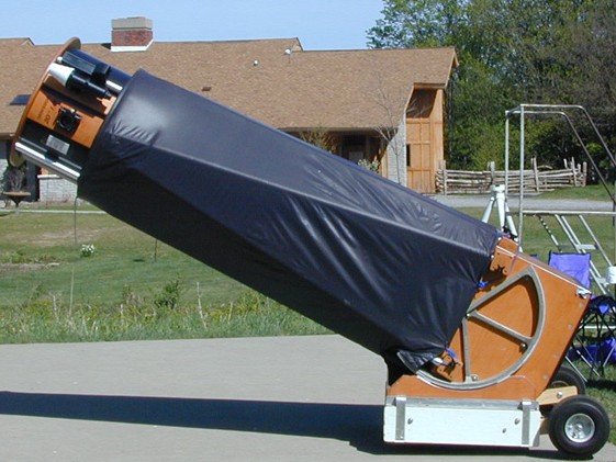 Fig 12. 50 cm Obsession Dobsonian.
 Fig 13. Inserting the mirror into the Obsession (don't drop it!)
 Fig 14. 71 cm string telescope.
 Fig 15. The 60 cm F/4 ultralight telescope.
 Fig 16. CAD drawings for a 56 cm F/4 Ultralight design.
Large aperture designs are publicised on the Internet and their designers can be emailed for further information. Mel Bartel's Web site https://www.bbastrodesigns.com provides links to many other ultra-light Dobsonian designs. However, there is a general lack of published plans for telescopes to accommodate a primary mirror of diameter as large as 48 cm. Neil noted that feedback from users of other large Dobsonians would no doubt help in the evaluation of potential designs and he made plans to visit the Thetford Star Party, 01-07 September 2002, to see some large aperture telescopes and meet their owners.
Slideset (Microsoft Powerpoint) discussed at the meeting, comparing many Dobsonian designs.
Attendees at the meeting represented a wide range of viewpoints, ranging from the enthusiastic, through the curious to the mildly sceptical. After the presentation, a healthy debate ensued about the merits or otherwise of the four designs and of the practicalities of constructing and using a 48 cm instrument. The key comments, questions and responses related to the latter were as follows.
Query / Comment
Response
The meeting agreed that questions regarding usage could only be answered properly following a detailed assessment of several designs against common assessment criteria.
By the end of the meeting, a consensus of opinion emerged to base the design of the Millennium Telescope loosely on Kriege and Berry's standard design (see figure 12). At this time, Neil's project plan for completion of the telescope comprised the following main activities:
Storage and assembly/disassembly appeared to be the hardest challenges to overcome given the dimensions and weight of the telescope. Neil intended to address these issues in detail once an initial view of the dimensions of the instrument (disassembled and assembled) was available. The next most important stages of the work were dimensioning, listing and costing the various components of the telescope and producing engineering drawings. In many cases, drawings and listings could be based on those in Kriege and Berry's book. Basic maths and physics skills were required but Neil was confident that the book would provide plenty of assistance. Later on, in the constructional phases, access to welding and woodworking tools would be required.
Neil arranged the second meeting of the Millennium Telescope project group for 10 July 2002 in the Orwell Park School Science Room. Participants presented and discussed requirements, design goals and some further design examples. The outcome of the meeting was as follows.
| Primary Mirror | Secondary Mirror | |
| Material: Pyrex | Material: plate glass | |
| Diameter: 482 mm | Major axis: 150 mm | |
| Edge thickness: 38 mm | Minor axis: 106 mm | |
| Focal length: 2165 mm | Thickness: 14.5 mm | |
| Focal ratio: F/4.5 |
Slideset (Microsoft Powerpoint) summarising requirements for the Millennium Telescope.
Following the second meeting of the project group, several members began informal meetings and discussions and undertook work on aspects of the design and construction of the telescope, mostly on Wednesday evenings. One of the first items upon which construction began was the mirror cell. The design was based on the Plop Drop mirror cell design software and other sources including Kriege and Berry; key aspects are as follows:
Figure 17 shows the cell during the early stages of construction, and figure 18 (taken on 26 November 2004) shows the finished version. (Also visible in the latter figure is the base of the telescope.)
 Fig 17. The mirror cell during early construction.
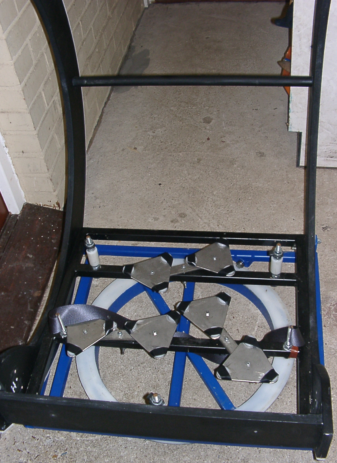 Fig 18. The mirror cell in completed form.
The 2002 Thetford (East Anglia, UK) Star Party was held 01-07 September. Paddy O'Sullivan and Neil Morley attended the final day of the Party hoping for an opportunity to meet the owners of large telescopes. Drizzly weather in the morning discouraged them from setting off for Thetford until after lunchtime and they arrived just after 2.00pm. Fortunately, the weather improved during the afternoon and gave them an excellent opportunity to meet people setting up their telescopes for the evening.
Neil and Paddy were surprised at the number of large Dobsonian telescopes present, both commercially produced and home-made. They counted five telescopes with apertures in excess of 38 cm. The largest was a 50 cm Obsession standing around 2.1 m tall. Neil regretted not bringing a camera (as well as missing an aurora visible on the previous night!) Telescope owners were more than willing to discuss their instruments and to share experiences and design tips, and Neil and Paddy took advantage of this in discussing the OASI design with them. One owner commented that large Dobsonians seem to be slowly replacing electronically controlled Schmidt-Cassegrains at star parties. In general, the Dobsonians at Thetford tended to be closer to the designs of Kriege and Berry, employing enclosed mirror cell assemblies, than to ultralight designs. This was encouraging, as it meant that the OASI design was at the leading edge of Dobsonian technology as far as the UK is concerned.
A summary of two designs seen at Thetford:
1. AstroSystems Telekit, USA
The Telekit (figure 19) is a commercially available telescope imported from the USA. It is supplied as a flat-pack kit requiring assembly and finishing. It is made almost entirely of ApplePly. Various sizes are available; Neil and Paddy saw a 45 cm model. The design incorporates several interesting features including a lightweight AstroSystems Crayford focusser made of what looked like resin material. The focusser employed four hex-wrench adjustments at its corners allowing its optical axis to be accurately aligned during collimation.
2. Kriege and Berry 50 cm Obsession
This design is illustrated in figures 12 and 13 above. An interesting design feature of the Obsession at Thetford was the use of a Novak secondary mirror holder: this looked rather like a small cake tin with the rim rolled over and turned in to prevent the mirror falling out (see figure 20). This is intended to minimise mechanical pinching of the secondary mirror and consequent image degradation.
The owner demonstrated how the secondary cage was attached to the truss tubes using commercially available fittings. This is the attachment mechanism favoured for the Millennium Telescope. Setup and takedown is a matter of seconds rather than minutes and can easily be completed by one person. The aluminium truss tubes are simply held against the edge of the tube-retaining assemblies by a simple aluminium wedge and cam lever assembly (see figure 21). The ends of the tubes are open; no threaded inserts are required to attach the tube to the attachment assembly. Note: components are attached by strings to the assembly to prevent them falling onto the primary mirror.
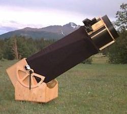 Fig 19. Astrosystems Telekit 45 cm.
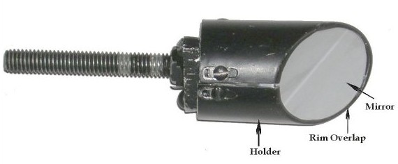 Fig 20. Novak secondary mirror holder.
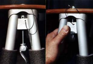 Fig 21. Obsession truss clamp.
Further design recommendations and lessons learned during the visit to Thetford were:
Slideset (Microsoft Powerpoint) summarising further design options for the Millennium Telescope.
On Saturday 16 November 2002, Paddy O'Sullivan and Garry Coleman cut the wooden side bearings and secondary cage of the Millennium Telescope from 18 mm HVHC (Hardwood Veneer Hardwood Core) plywood. The timber was supplied by Holdens on Duke Street, near Ipswich Docks. Cutting took place in Garry's workshop.
The first stage of the job was marking the cutting measurements on the HVHC. Garry marked the measurements to dimensions specified by Paddy (figure 22). Once the HVHC was cut, it would be too late to rectify any mistakes in measuring, so the pair spent at least 45 minutes checking the measurements and, in fact, made a few alterations, proving that the time devoted to quality control was well spent! Once completely confident that the marking was correct, Garry cut the HVHC to shape using a router fixed in a jig. The router and jig are worth a few words of explanation. Figure 23 shows a close-up of the underside of the router: it was a plunge router with a tungsten carbide cutting tip which provided an extremely clean, vertical, repeatable cut. Paddy and Garry fixed the router in a jig to ensure accurate cutting. They used G-clamps to attach wooden stops to the ends of the cutting track to prevent the router/jig assembly from exceeding the measured dimensions and causing safety concerns. Figure 24 shows Garry repositioning the router and jig between cuts. After setting the jig, before each cut, Garry moved the router around the cutting line to check that there were no obstacles in the way. Once the preliminaries were completed, Garry commenced routing: see figures 25 and 26.
The cutting depth was set at 3 mm and Garry made multiple passes to cut through the timber completely. This approach was lengthy but avoided generating lots of swarf and sawdust and minimised overheating the cutting tip. To further minimise the quantity of dust generated, the router was coupled via a hose to a vacuum cleaner which automatically turned on and off as necessary. Despite the vacuum cleaner, it was still necessary following each pass of the router to clean the timber of swarf and sawdust - see figure 27. A chisel was used to remove "whiskering" at the edges of the cut. The whiskering was almost certainly due to the hardness of the wood.
The result of the day's work was to produce two "sledge-runner" side bearings and the secondary cage ring.
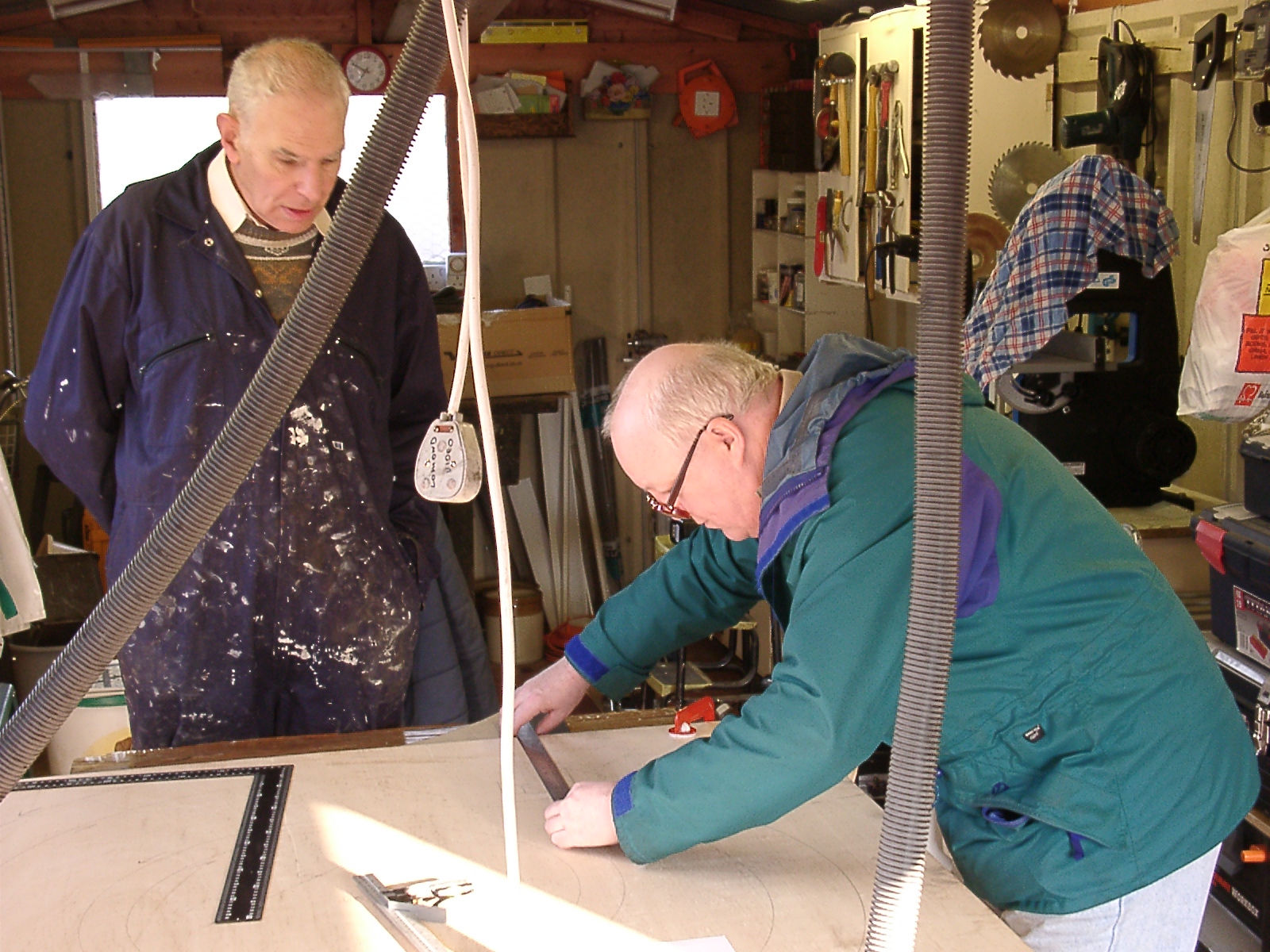 Fig 22. Checking measurements.
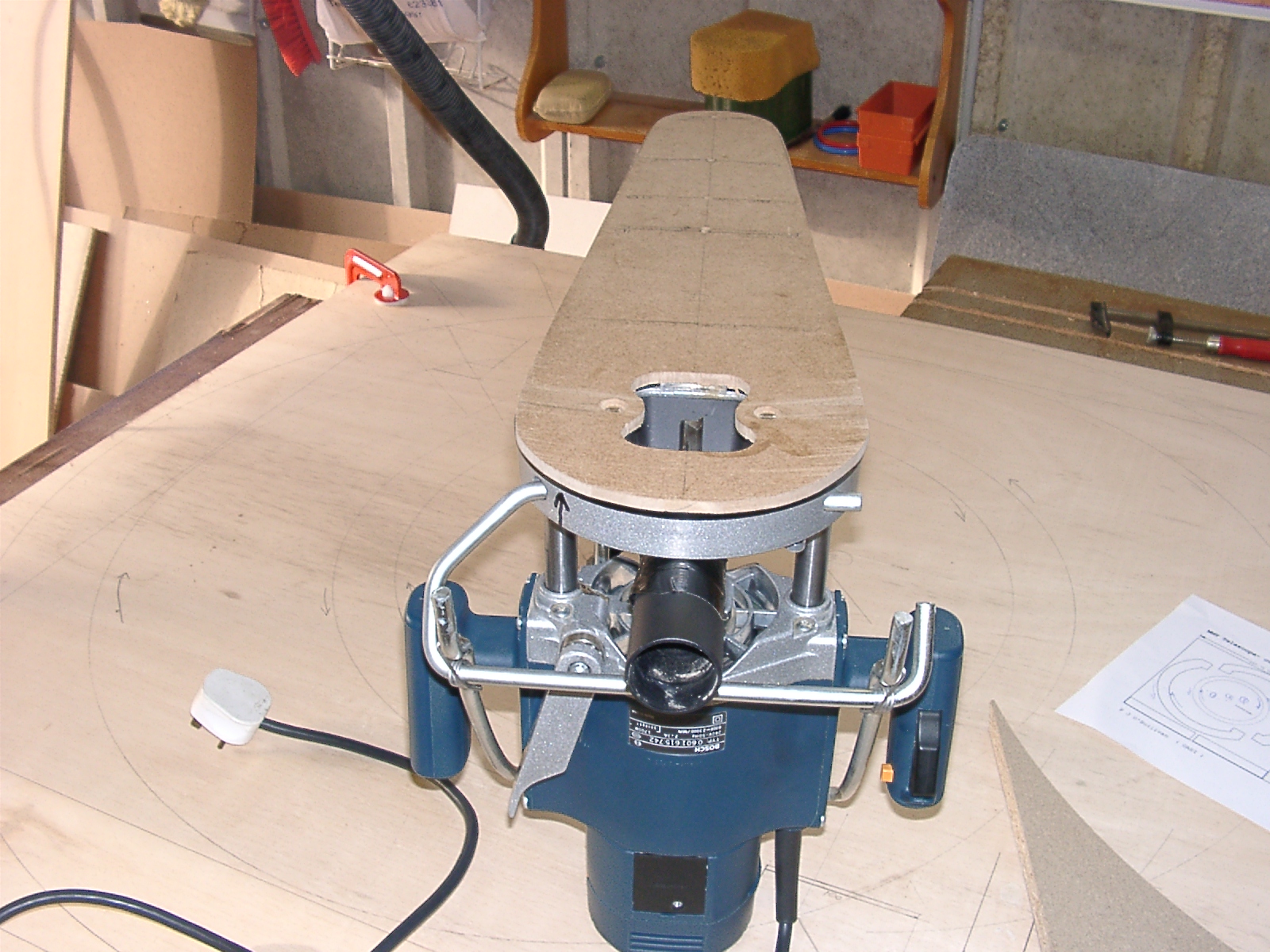 Fig 23. Underside of router.
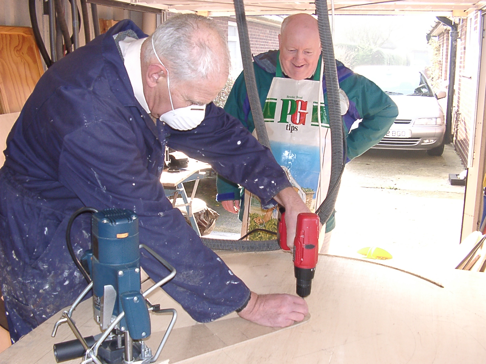 Fig 24. Repositioning the jig.
 Fig 25. Routing the side bearings.
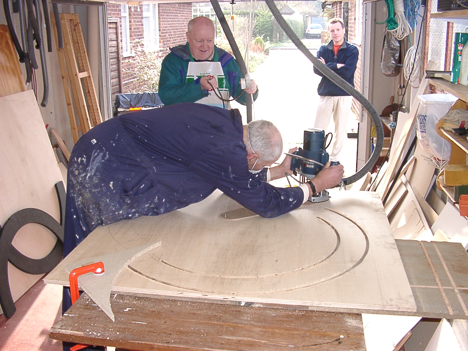 Fig 26. Routing the side bearings.
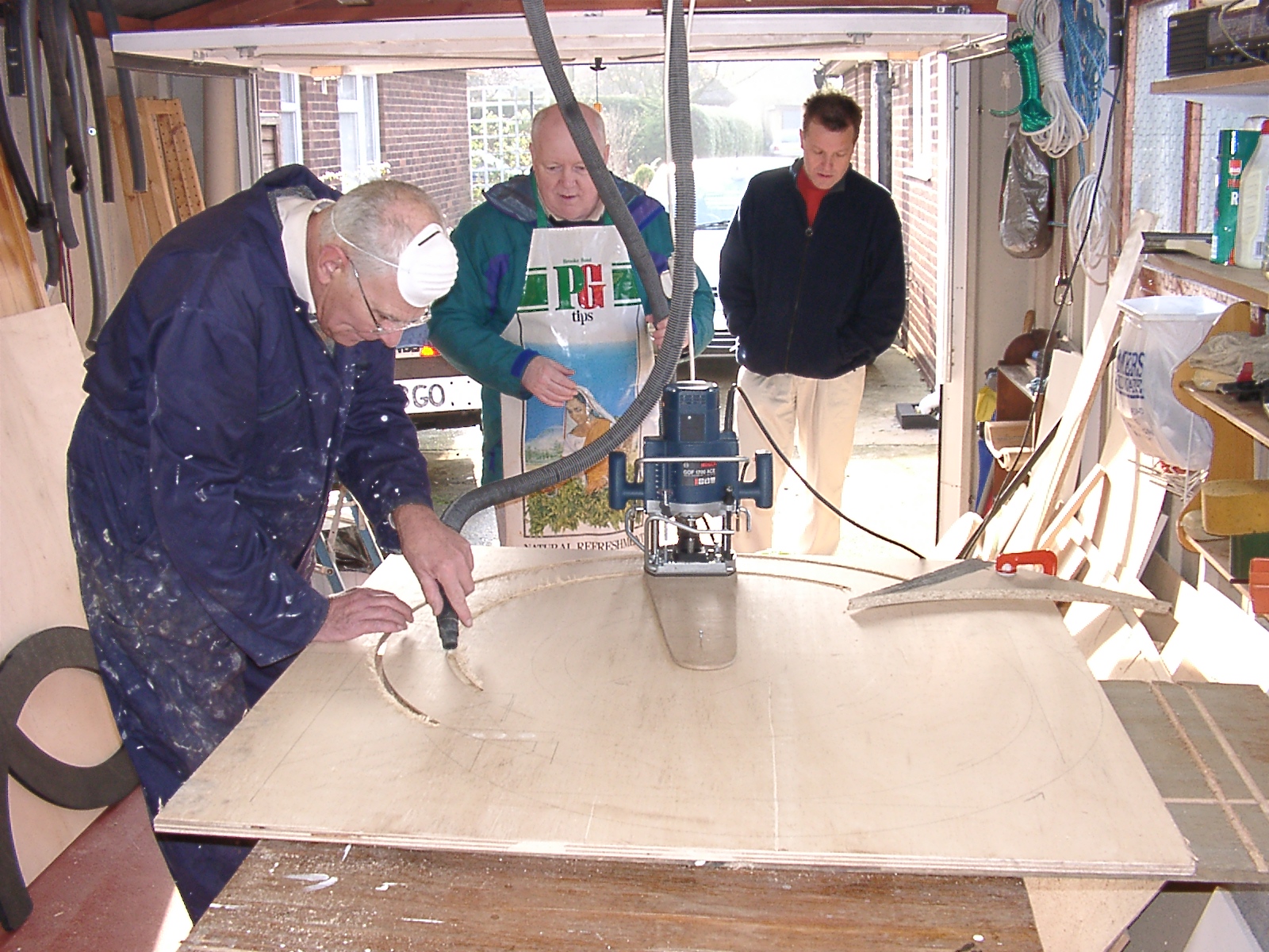 Fig 27. Cleaning after a cut.
Figure 28 shows the oil drum which Mike Harlow used as a stand for polishing the secondary mirror. The original top of the drum has been removed and replaced with a wooden platform with cleats to hold the mirror.
Mike's strategy was first to polish the 220 mm f/6 mirror that members of OASI ground in 1998. This provided practice before polishing the secondary of the Millennium Telescope itself. Polishing the 220 mm mirror began on 02 March 2003 (figure 29) and polishing the secondary mirror of the Millennium Telescope began three days later (figure 30). Note that the secondary is blocked up with scrap pieces of glass to make a disk.
Initial figuring of the secondary mirror achieved an accuracy of approximately 10*lambda/2. Subsequent work reduced the error to about lambda/2 over most of the usable area. There was some edge roll-off which had to be corrected, although the extreme edge will be hidden by the secondary holder. Figure 31 (taken 11 March 2003) shows the secondary under test in contact with an optical flat (lambda/8) illuminated by monochromatic light from a helium-neon laser (632.8 nm). It shows the secondary near to completion of figuring.
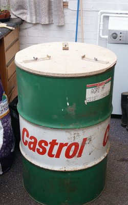 Fig 28. Oil drum used as a stand for polishing the secondary.
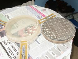 Fig 29. Polishing the back of the 220 mm mirror.
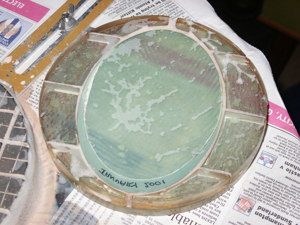 Fig 30. Polishing the secondary mirror of the Millennium Telescope.
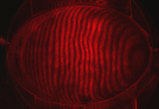 Fig 31. Foucault test of the secondary mirror shortly before completion of figuring.
During spring 2003, Neil hosted evening meetings to finalise details of the assembly of the telescope. Figure 32 shows Neil, Garry and Paddy at a planning meeting on 25 March 2003. Once details of the assembly were clarified, work proceeded apace.
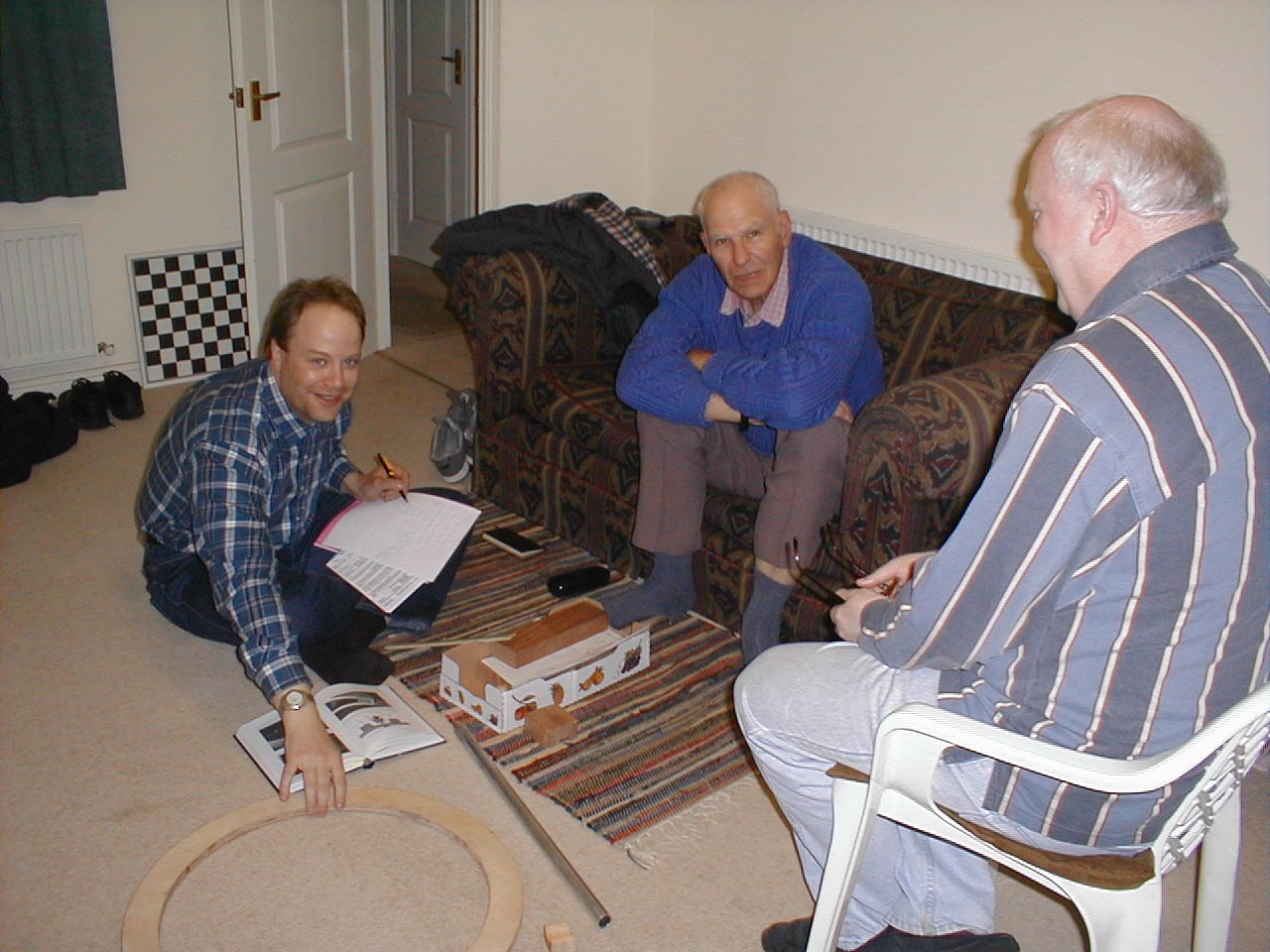 Fig 32. Neil, Paddy & Garry at a planning meeting, 25 March 2003.
Assembly began on 04 April. Martin Cook, Paddy O'Sullivan and Garry Coleman gatherered in Garry's garage to progress the work. (OASI expresses thanks to Garry for allowing the Society use of such excellent facilities!) Assembly commenced by securely bolting the metal primary mirror cell structure to one of the two wooden "sledge-runner" side bearings. First, one of the side bearings was laid flat on its side and marked for drilling. Using a drill extender passing through the pre-drilled mirror cell assembly, Martin drilled three holes in the side bearing to accommodate bolts and then securely bolted it to the mirror cell assembly using carriage bolts. Figure 33 shows Martin and Garry checking correct orientation of the side bearing and correct marking of holes prior to drilling, figure 34 shows Martin drilling through the mirror cell assembly into the side bearing and figure 35 shows the mirror cell assembly bolted to the side bearing with Martin attaching an additional tubular bracing strut to enhance the structural integrity of the overall mirror support system.
The next task was to attach the second side bearing to the mirror cell structure. Figure 36 shows Paddy attaching the second side bearing to two points: the bracing strut and a central hole within the mirror cell assembly (already drilled). This arrangement allowed adjustment between the relatively movable upper side bearing and fixed lower side bearing. Martin, Paddy and Garry then placed the entire mirror support system onto a level surface to facilitate correct alignment of the side bearings with one another: the garage floor was not completely level, so they used as flat surface a board placed on the floor levelled by wedges at the corners. Accuracy was paramount! Figure 37 shows Martin using a spirit level to adjust the relative position of the side bearings. He placed the spirit level across the mirror cell between the side bearings both at the near end as shown here and at the far end and adjusted the movable side bearing until the spirit bubble was level. Once this had been achieved, the upper side bearing was securely clamped in position in preparation for drilling the two remaining holes. These very important steps took some time to complete and were critical towards ensuring a smooth movement of the telescope in the elevation axis. Time well spent! Figure 38 shows the upper side bearing securely clamped in place and Martin starting to drill the two remaining holes. The drill passed all the way through! Figure 39 shows the mirror cell securely bolted to the side bearings, the metal bracing strut, two wooden "end battens" and clamps for the Serrurier truss poles; Garry and Martin are discussing the positioning of two of the lower clamps.
In figure 40, Martin demonstrates the structural integrity of the primary assembly! Figure 41 shows Martin and Paddy transporting the primary mirror system: without the mirror, this presents little difficulty!
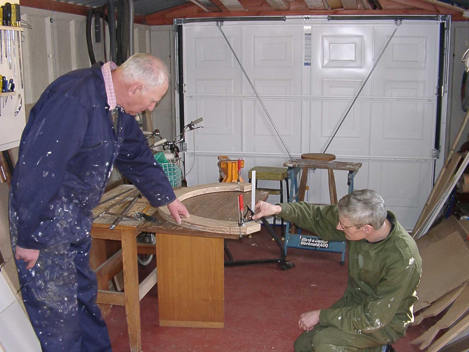 Fig 33. Checking the side bearings.
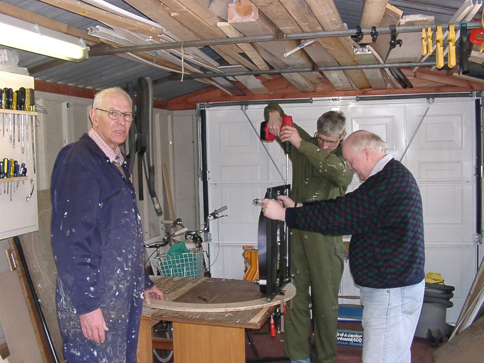 Fig 34. Drilling a side bearing.
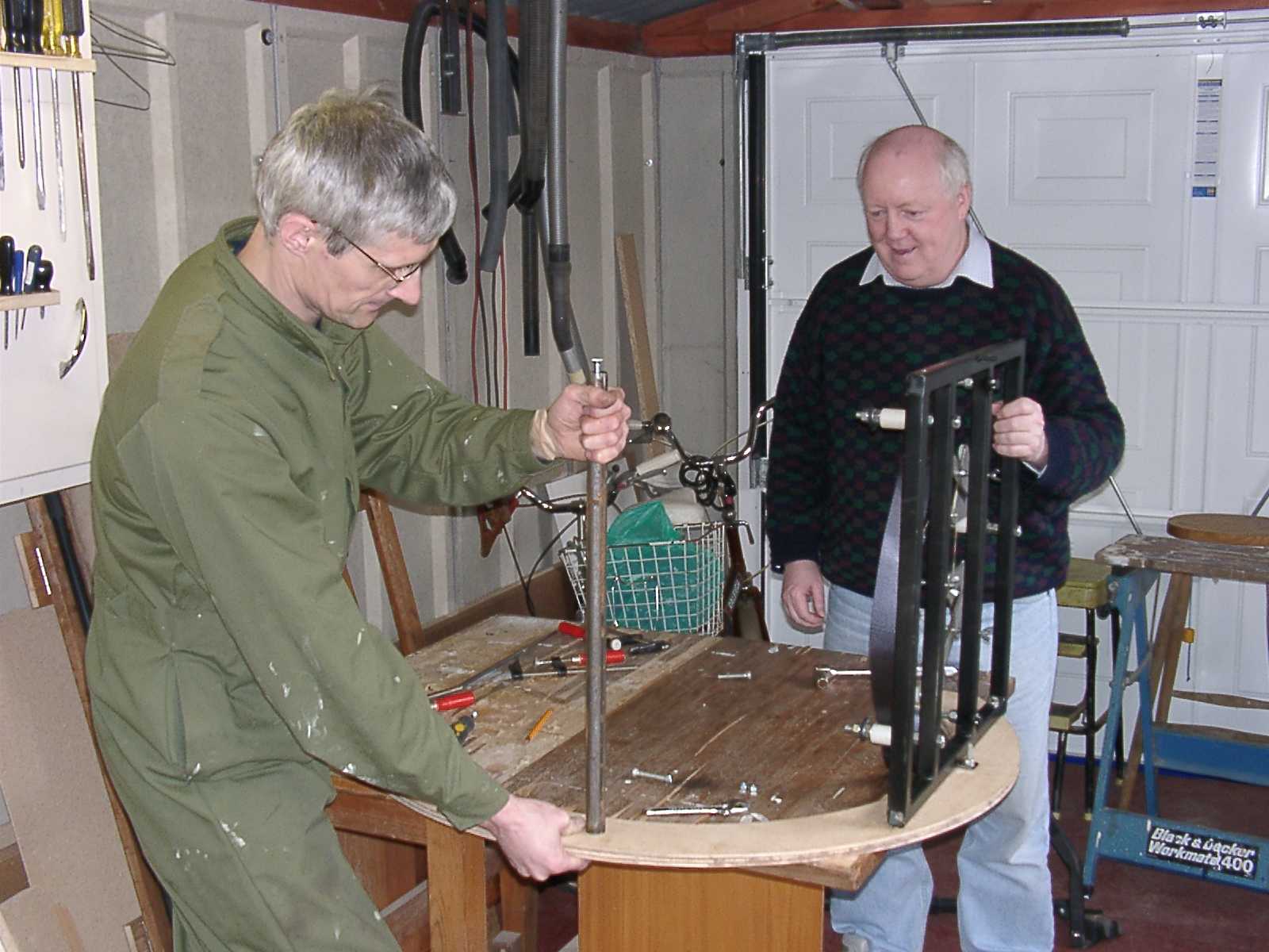 Fig 35. Attaching a bracing strut.
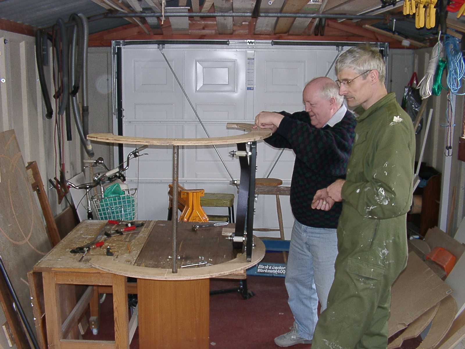 Fig 36. Attaching the upper side bearing.
 Fig 37. Adjusting the side bearings.
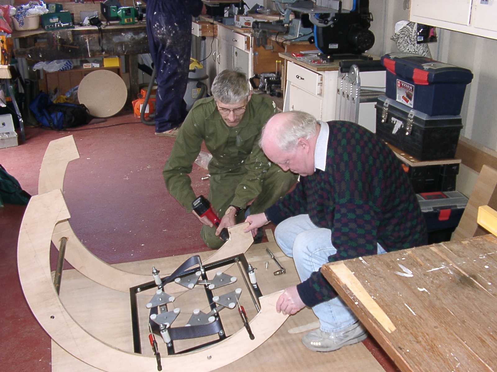 Fig 38. Drilling into the second side bearing.
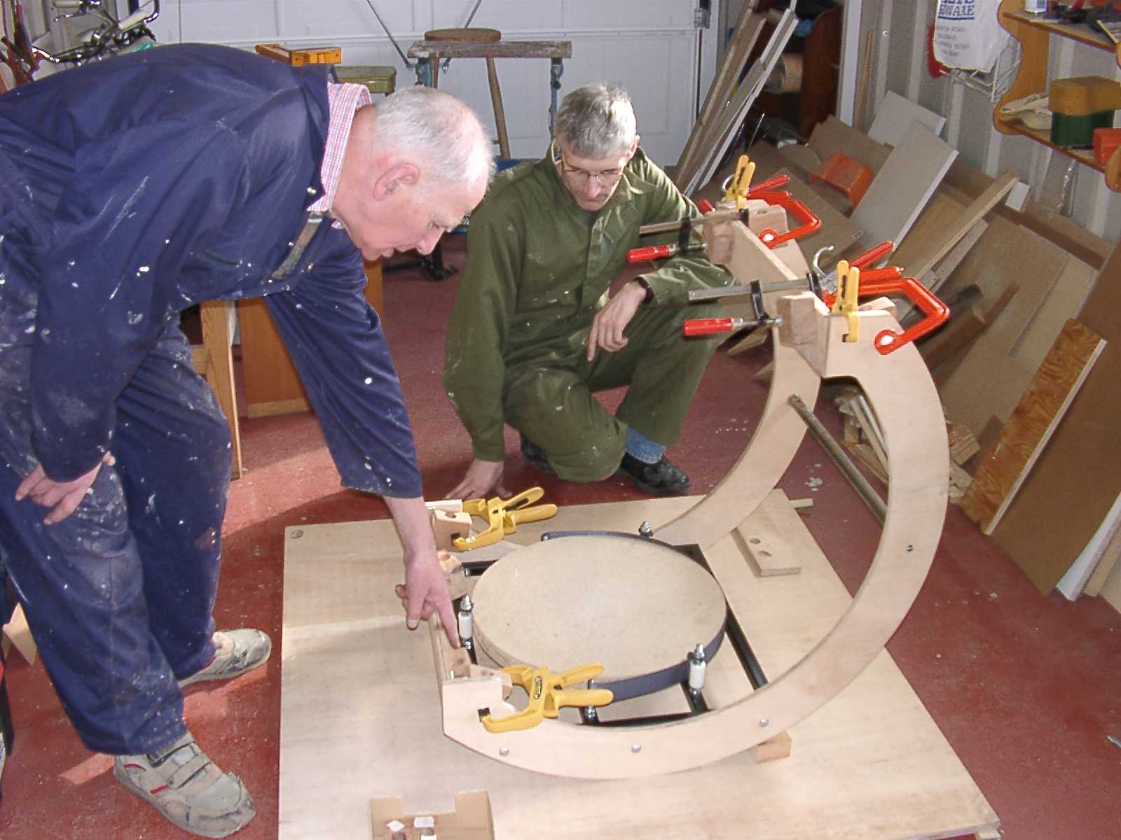 Fig 39. Assembled mirror support system.
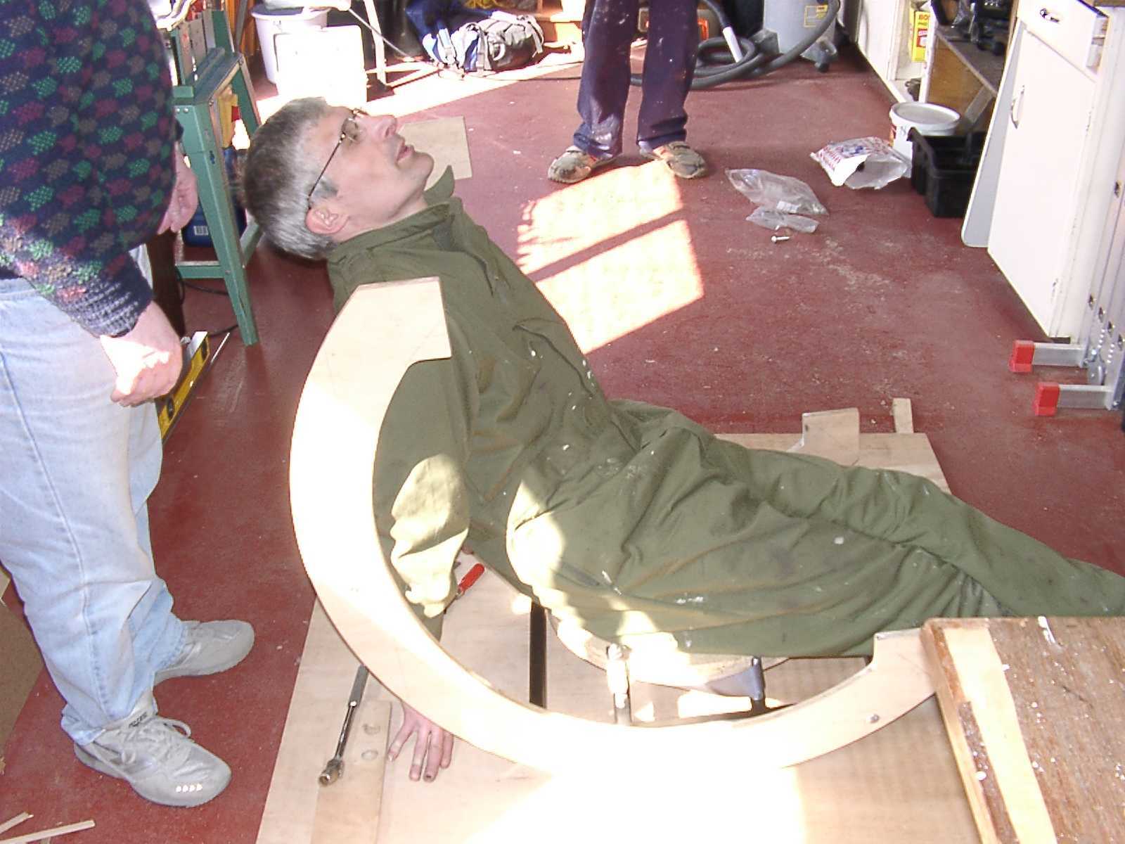 Fig 40. Testing the structural integrity of the mirror support system!
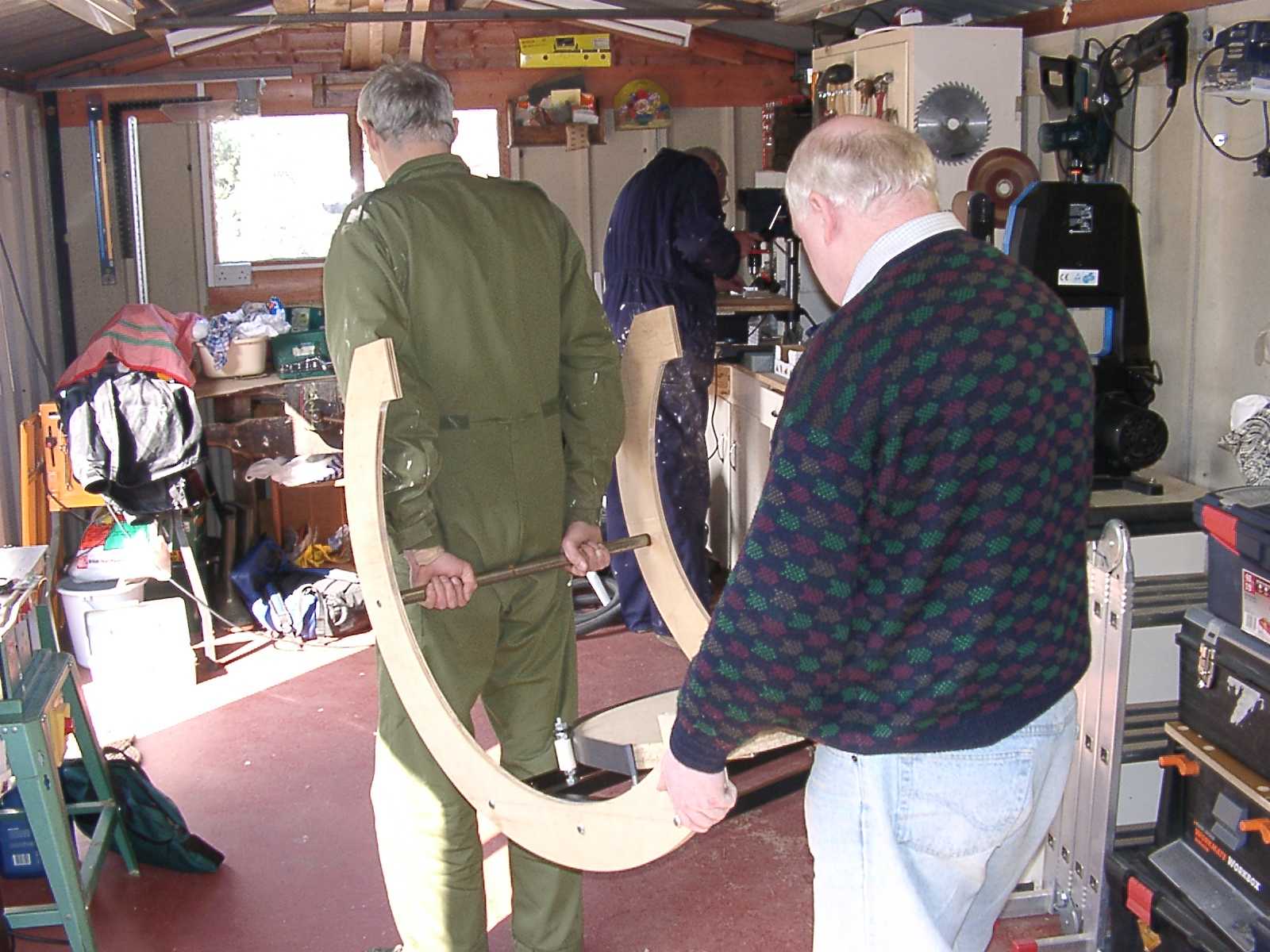 Fig 41. Transporting the mirror support system.
The project team achieved a major milestone on 25 April 2003, when the telescope frame was assembled in its entirety. Figure 42, taken once more in Garry's garage, shows, for the first time, truss poles inserted in the wooden clamps in the primary mirror system. Figure 43, taken a few minutes later, shows the instrument with the secondary ring and spider attached. Assembly was a memorable occasion and marked a fabulous team effort after all the hard work that went into design and construction in the preceding months. Assembly took only 10 minutes. (One key component awaiting final construction, and not shown in the photo, is the base, which provides azimuth and elevation movement.)
The following day, the frame was transported to Orwell Park School for display at a committee meeting - see figure 44. The components of the telescope fitted easily into Paddy's Volkswagen Golf hatchback and assembly took less than five minutes (after unloading), demonstrating compliance with the requirement for easy transportability!
The three major components shown in the photograph are the primary mirror support system, truss tubes and secondary cage. Four pairs of tubes attach the secondary cage to the primary mirror support assembly and wooden clamps and wedges attach the tops of the poles to the secondary cage via a single bolt through each of the four wedges. The three-vane pyramid spider and secondary holder can be clearly seen. This photo provides an indication of the size of the telescope when assembled. Tube lengths have been oversized by around 150 mm at this time; however, the reduction in height of the telescope when they are cut to the correct lengths will be offset by introducing a base of similar height. A stepladder will be required for viewing objects at or near the zenith.
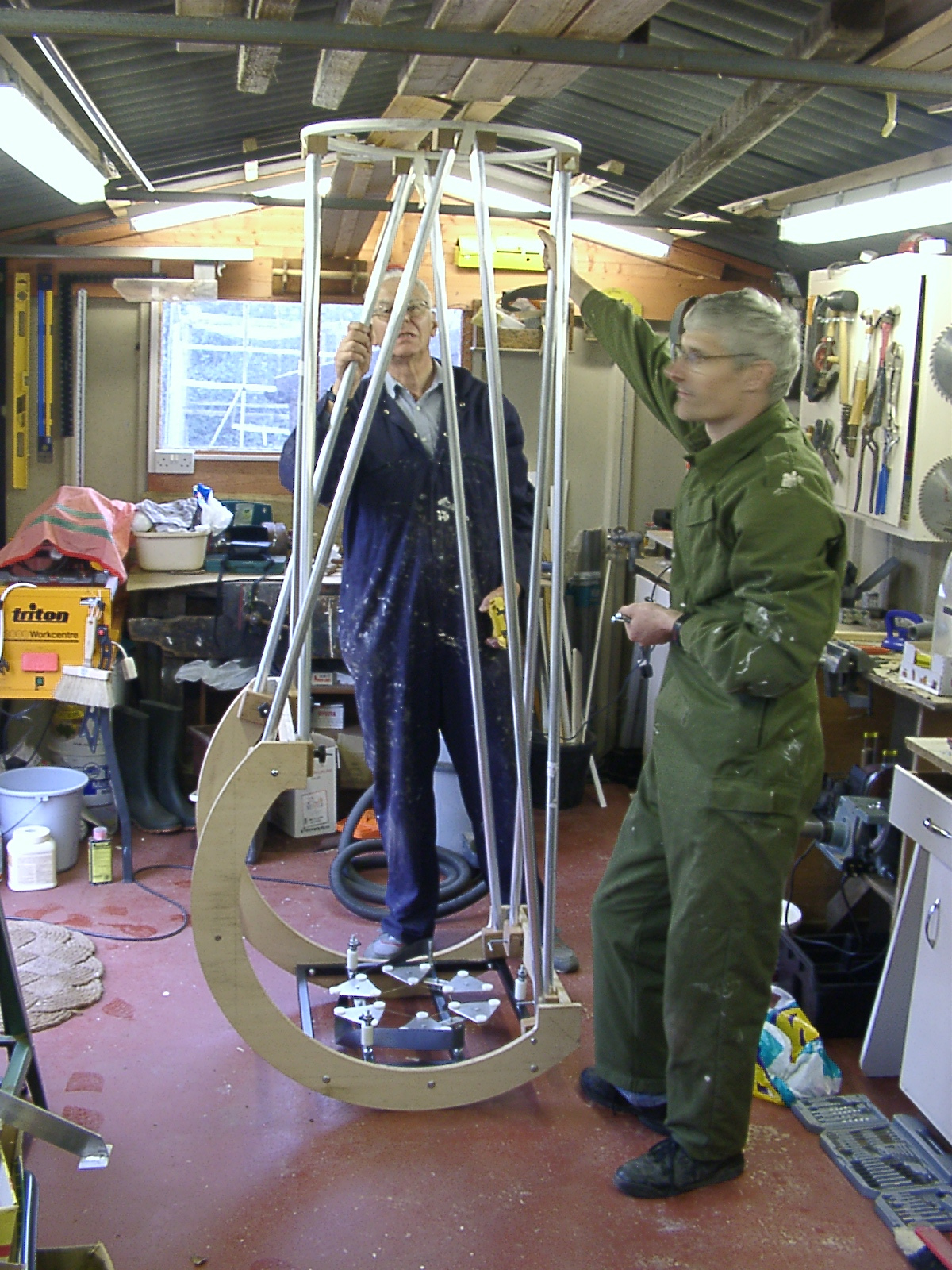 Fig 42. First assembly of the telescope frame.
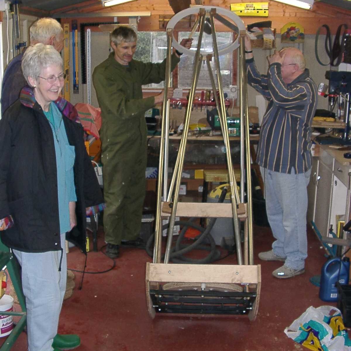 Fig 43. First assembly of the telescope frame.
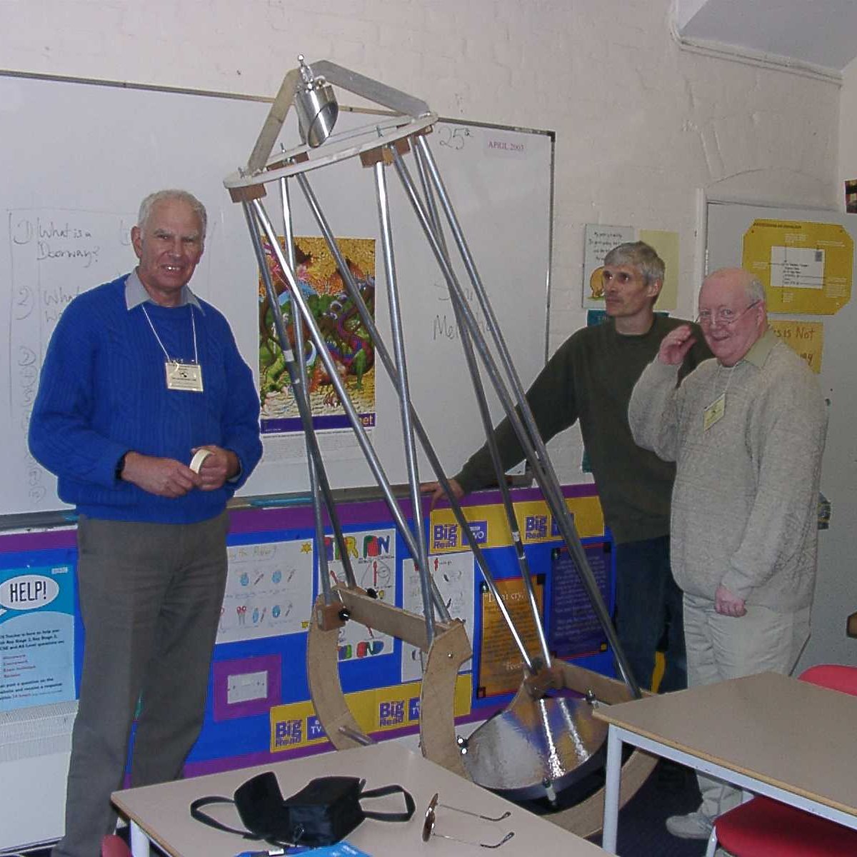 Fig 44. Telescope frame assembled at the committee meeting.
Mike Harlow began polishing the primary mirror on the afternoon of 19 June 2003. At the end of the first session, the mirror was uniformly clear enough to read newsprint through. At this time, Mike estimated that a further six hours polishing would be required to achieve an optical finish but, in fact, only three hours were required for this. However, in the end Mike did devote some six hours to polishing to ensure a completely pit-free surface. Figures 45-48 show polishing in progress and the result. Note that the polishing lap is some 28 cm in diameter, considerably smaller than the mirror itself. This works just as well as a full-size polisher, albeit more slowly, and actually makes figuring easier.
At the end of polishing, on 23 June 2003, Mike conducted the first Foucault test on the primary mirror. The curve looked smooth and exhibited about 40% of the full correction, providing a good starting point for figuring. Mike measured the radius of curvature at 4400 mm, implying a focal length of 2200 mm. However, figuring involves deepening the curve, so he expected the focal length to decrease slightly during the work, probably by several millimetres.
After completing polishing, Mike began figuring. By the end of June, after a week of work, the mirror was diffraction limited – but only at 3 microns, suitable for astronomy in the infra-red but not in visible light! As Mike approached the final figure, progress became ever slower, with a typical cycle of activity consisting of some 10 minutes of figuring, followed by a rest of an hour or so to allow the mirror to cool, followed by testing. He had to exercise great care to prevent contamination of the glass. At this stage he hoped to complete the mirror by the end of July 2003.
Mike recorded progress in an Excel spreadsheet. Figure 49 is an extract from the spreadsheet showing progress after one week of figuring: it displays knife-edge measurements (with the dimensions of the ideal parabola subtracted) as a function of the radius. With this scaling, the perfect profile for the mirror is represented by a straight line along the horizontal axis and the tolerances (1/8 wave) by the two red curves above and below it; the actual measurements are shown in blue. Note that the red tolerance lines get closer towards the edge of the mirror: that is what makes it difficult to figure accurately! All measurements, shown in blue, must end up within the tolerance curves (red) to ensure a mirror that is sufficiently accurate to deliver good visual performance. Clearly, after one week of figuring, a lot of work remained! At the time, Mike was using a 28 cm polishing lap. The literature suggested that a small diameter lap was more suitable for figuring large, fast mirrors so he cut a new 15 cm diameter disc to form a new one.
By mid-July 2003, Mike had also made progress with the secondary mirror (see figure 50). He first ground the edge so that it would fit into the mirror cell, then thoroughly cleaned it and applied an initial aluminium coating to assess the quality of the surface – the results were very good, although a little figuring remained to be done.
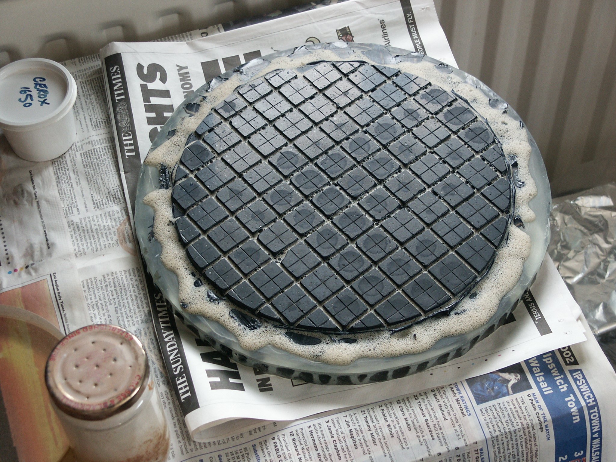 Fig 45. Polishing tool for the primary mirror.
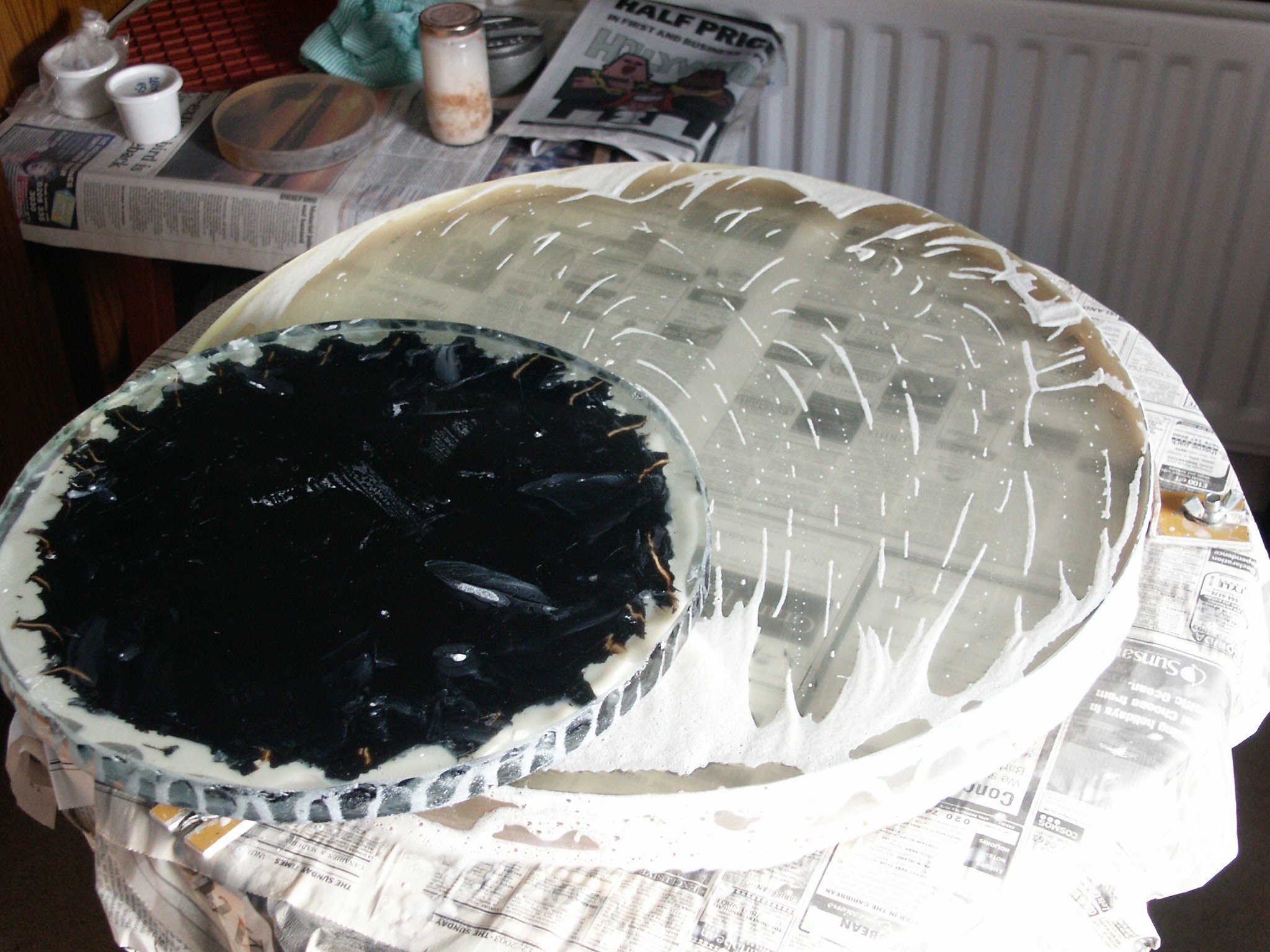 Fig 46. Polishing the primary mirror.
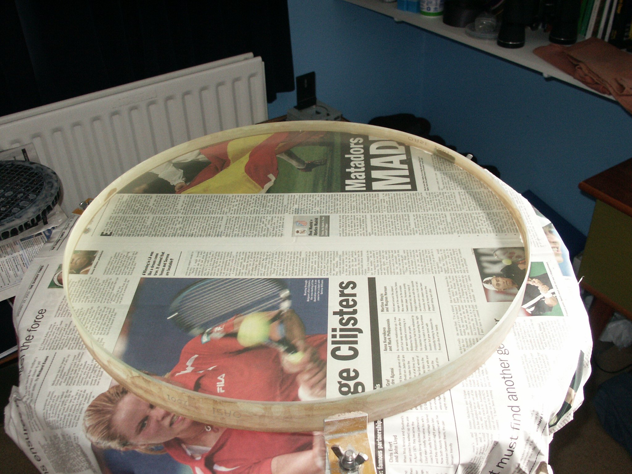 Fig 47. The primary mirror after completion of polishing.
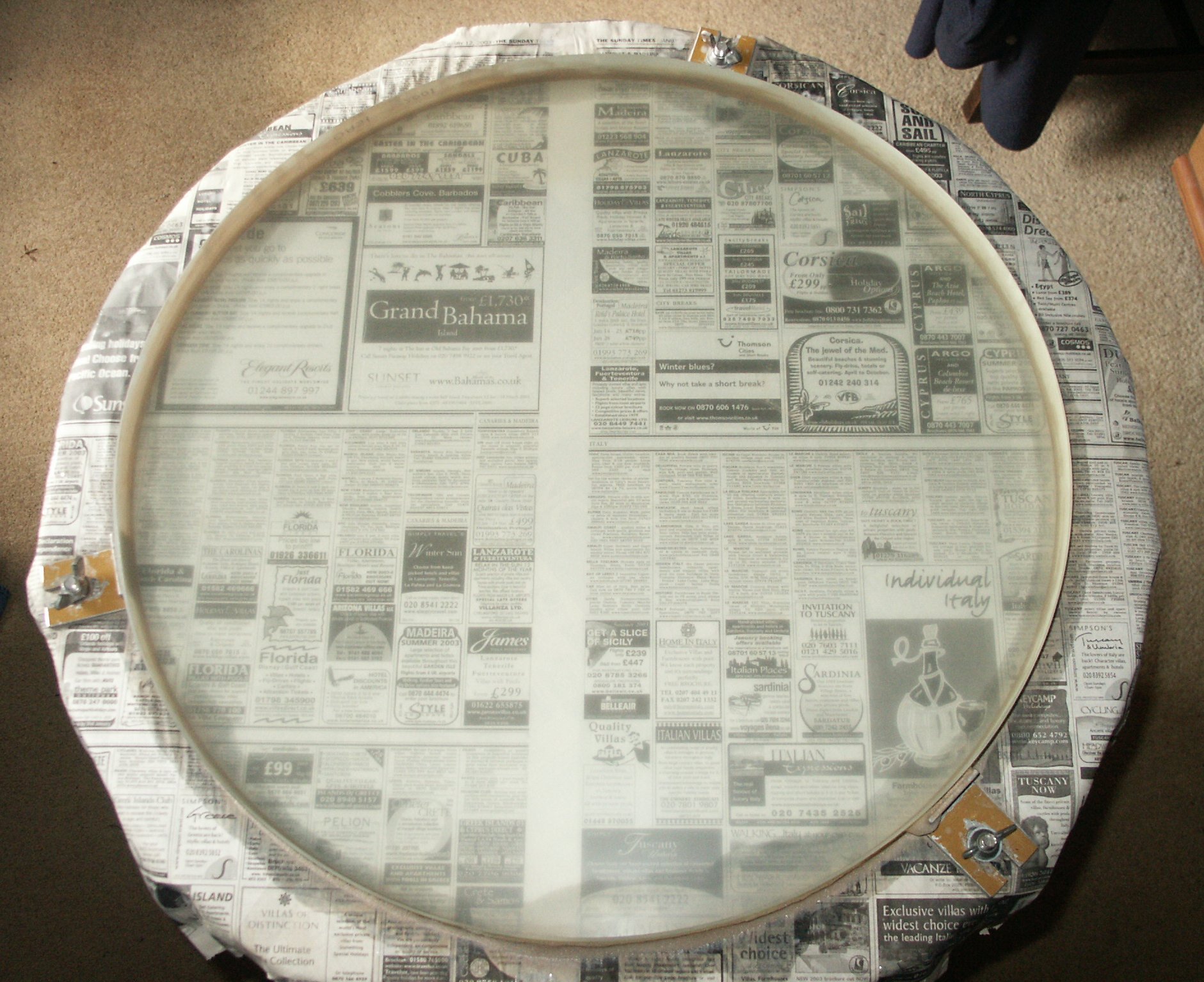 Fig 48. Newsprint legible through the fully polished primary mirror.
 Fig 49. Knife-edge measurements on the primary mirror.
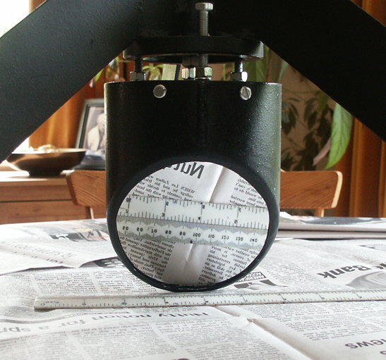 Fig 50. Secondary mirror after trial aluminising.
Figures 51 and 52 show the Millennium Telescope frame on display at Thetford Star Party on 27 September 2003. The telescope rocker, tubes and secondary cage are visible, but the pyramid spider / secondary holder and base were not present. The primary mirror is a wooden dummy covered with silver foil.
Figure 53 is a photo of the telescope taken by former BAA President Martin Mobberley at the OASI-SPA meeting, St Mary Magdalene Church Hall, Ipswich, 04 October 2003. Again, the primary mirror is a wooden dummy covered with silver foil.
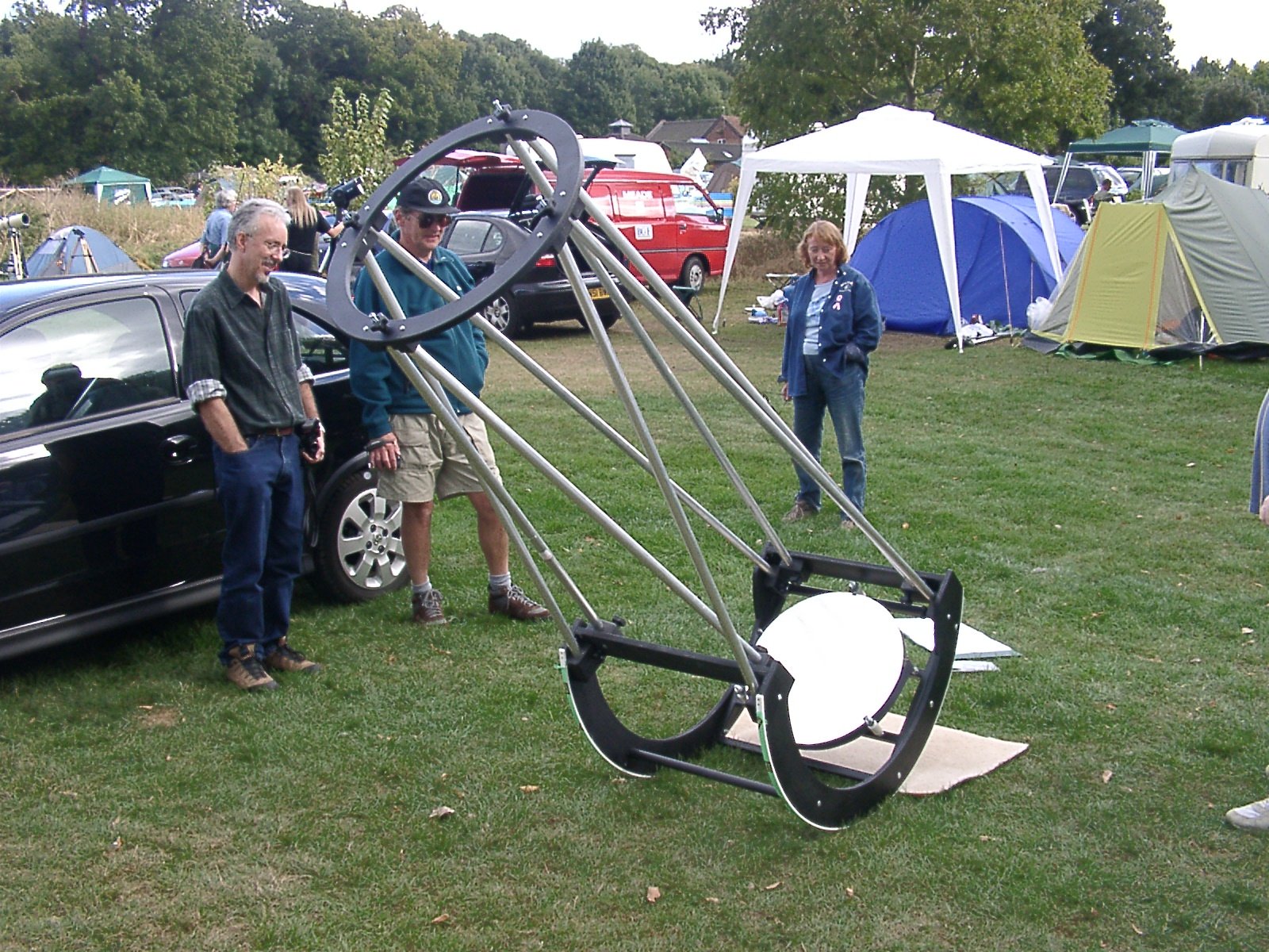 Fig 51. Frame of the telescope at Thetford Star Party 2003.
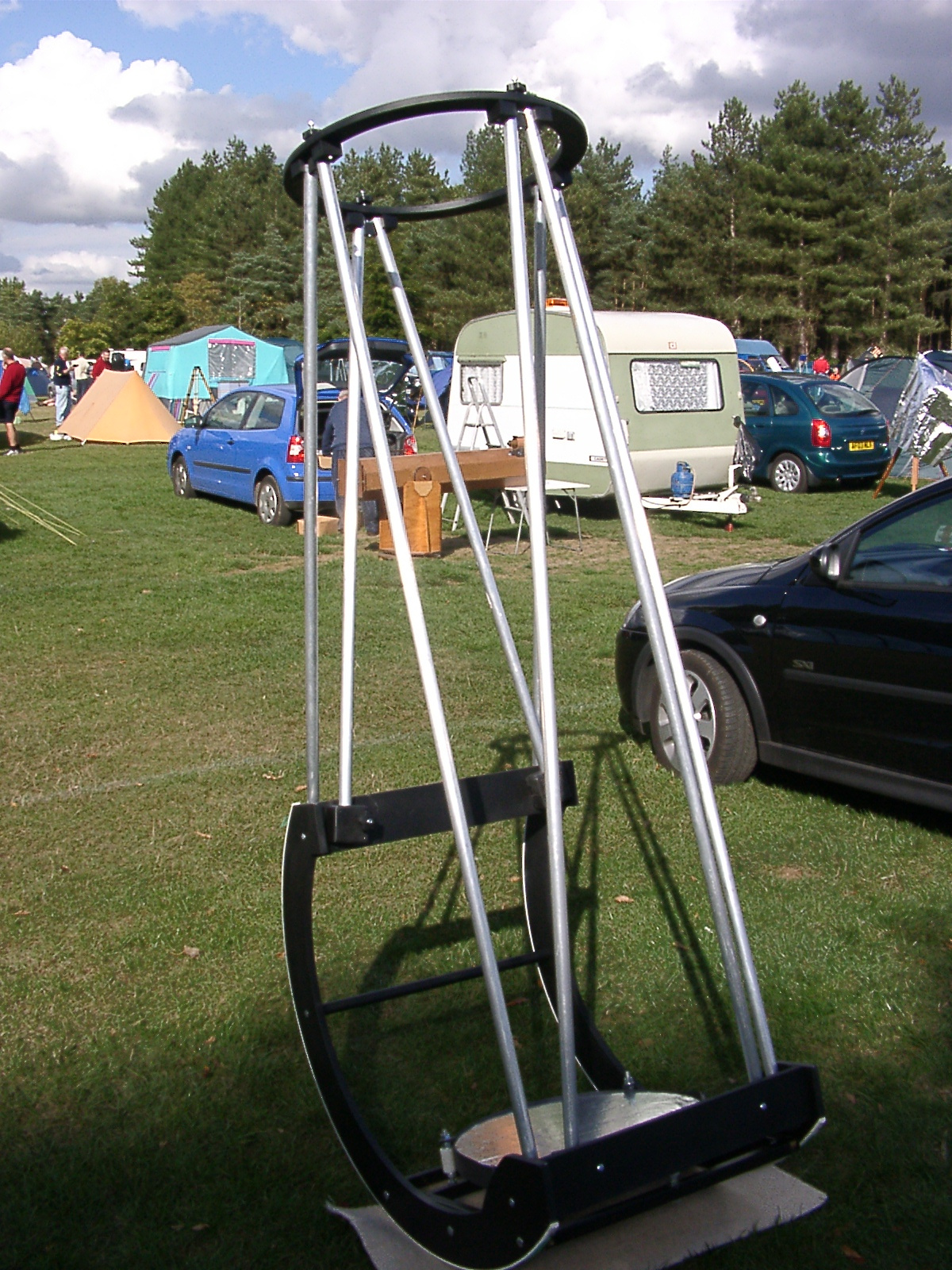 Fig 52. Frame of the telescope at Thetford Star Party 2003.
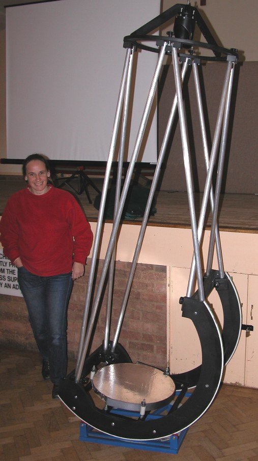 Fig 53. Frame of the telescope at OASI-SPA joint meeting, 04 October 2003.
By October 2003, it was becoming apparent that figuring the 48 cm main mirror was an extremely challenging task, possibly beyond the abilities even of a skilled amateur telescope maker such as Mike Harlow. Initially, Mike believed that the difficulty lay with the polishers. The then new book, A Manual for Amateur Telescope Makers (published by Willmann-Bell) provided new ideas including fresh ways of making polishers. Mike adopted an approach recommended in the book to create a new lap which he hoped would perform much better than the previous one; figures 54-56 illustrate its production.
He then continued figuring with the new lap. Although his initial estimates were that figuring could be completed within a few months, by late 2003 it had become apparent that the difficulties of accurately figuring such a large mirror were immense and that outside assistance could be required. Neil Morley then began looking for commercial options to complete the work. By early 2004, it was apparent that Mike could not complete the task and, with the thanks of the committee for the sterling work that he had successfully completed on the mirror, abandoned further efforts. OASI then arranged for Jim Hysom of Cambridge to finish the task. Figure 57 shows Mike Harlow fitting the unfinished mirror into the frame of the instrument on 13 March 2004.
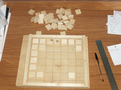 Fig 54. Cutting the mould for the new lap.
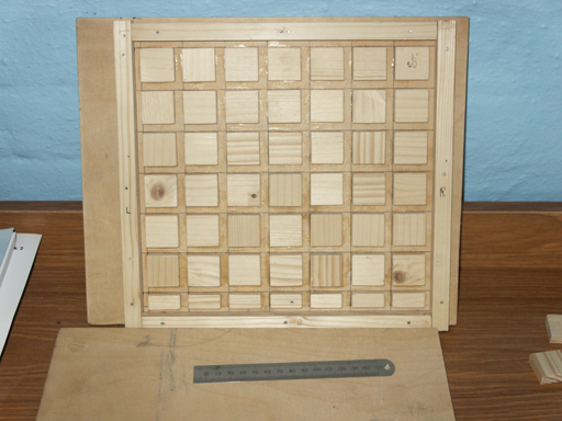 Fig 55. Completed mould for the new lap.
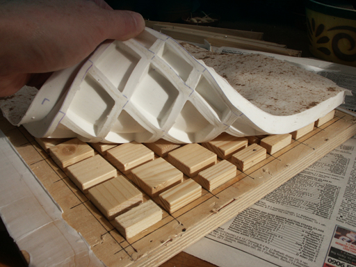 Fig 56. Removing the lap from the mould.
 Fig 57. Mike Harlow fitting the unsilvered primary mirror into the frame.
On Saturday 06 November 2004, Paddy O'Sullivan, Neil Morley, Martin Cook and Garry Coleman once more gathered in Garry's garage. Their aim was to undertake the first full assembly of the Millennium Telescope to check all components and verify the mechanical alignment of the optics. Figure 58 shows the frame assembled outside the garage, with a plumb bob being used to check alignment. Figure 59 shows the secondary mirror, figured and silvered by Mike Harlow, being inserted into its holder. The primary still required final figuring and was therefore unsilvered, and figure 60 shows newsprint clearly visible through it.
Even through the primary mirror was unsilvered, it still reflected some light, and those present were able therefore to use the telescope by holding an eyepiece in line with and just outside the focusser. Through this approach, in the fading daylight, first light revealed an image of leaves on a distant tree.
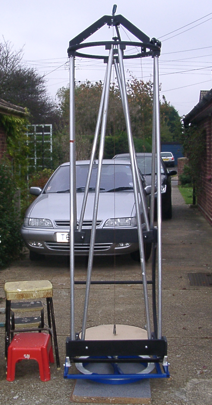 Fig 58. The telescope frame.
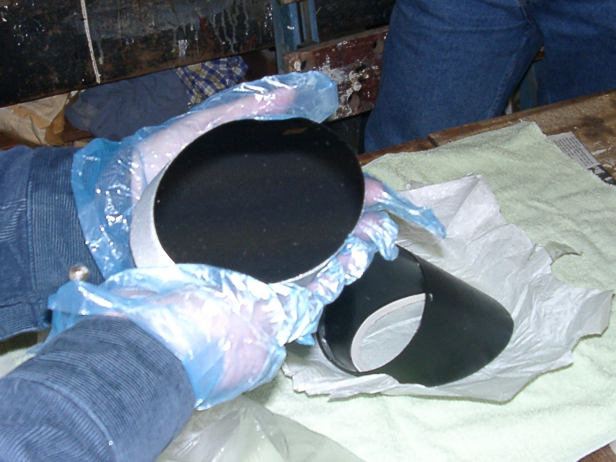 Fig 59. Fitting the secondary mirror to its holder.
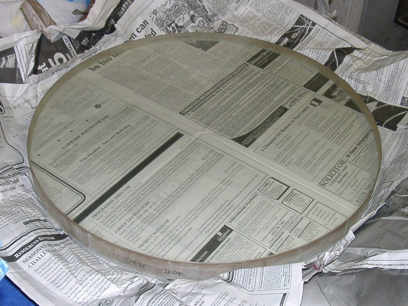 Fig 60. Newsprint clearly visible through the unsilvered primary mirror.
The following day, the group reassembled. The first task was to shorten the Serrurier poles by 80 mm (they had been initially deliberately over-sized). Using a 50 mm diameter Meade 32 mm eyepiece, the telescope then provided good focus on a spruce tree at 200 m distance. Although the main mirror was unsilvered, detail of individual pine needles could be discerned. The right angled 8x50 mm finder-scope was easily aligned and worked as expected. The Crayford rotary focuser worked very well - but Martin aimed to replace the central tube with a longer one to accommodate the focal length variation needed to use all OASI's eyepieces.
After viewing pine needles at 200 m distance, in an effort to get closer to astronomical distances, the observers moved the telescope into the road outside Garry's house and focussed on the Heath Road Hospital chimney some two kilometres away. They could see the multiple chimney stacks and lots of detailed structure.
The friction of the block and rollers was about right: the telescope moved smoothly and easily and, once pointed, it remained in position. The balance was good with the top ring fully populated: balance weights proved unnecessary. (The Microsoft Excel balance spreadsheet proved to be right after all!)
At the conclusion of a very successful weekend, the main remaining tasks of the project were:
Paddy, Neil, Martin and Garry were optimistic that at long last, completion of the Millennium Telescope project, conceived in 1998 and upon which work started in earnest in 1999, appeared to be within grasp!
Shortly after Jim returned the completed mirror, on Monday 18 April 2005, Paddy O'Sullivan, Neil Morley and Martin Cook performed the first full assembly of the Millennium Telescope with silvered primary mirror. Figure 61 shows the assembly of the frame, and figure 62 shows the mirror immediately prior to fitting (note the image of the Moon to centre bottom). Following assembly and careful checking, the three went on to observe the Moon (figures 63 and 64). The observers agreed that the image quality was excellent, revealing considerable detail on the lunar surface. Further improvements are expected once collimation of the telescope is completed.
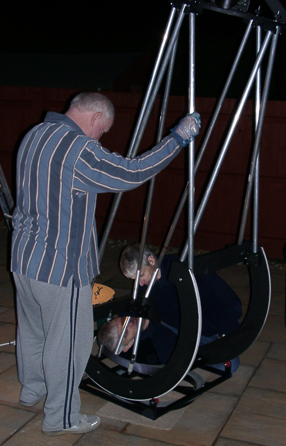 Fig 61. Assembling the telescope.
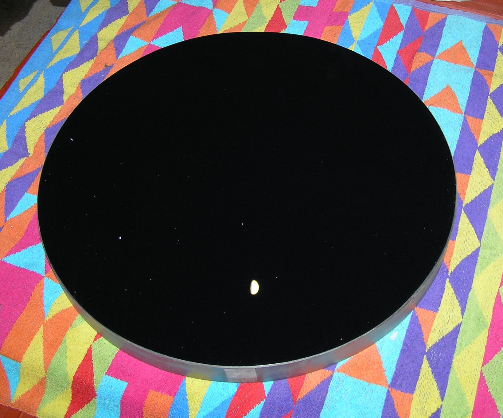 Fig 62. The primary mirror, silvered, awaiting installation in the mirror cell. Note the image of the Moon to centre bottom.
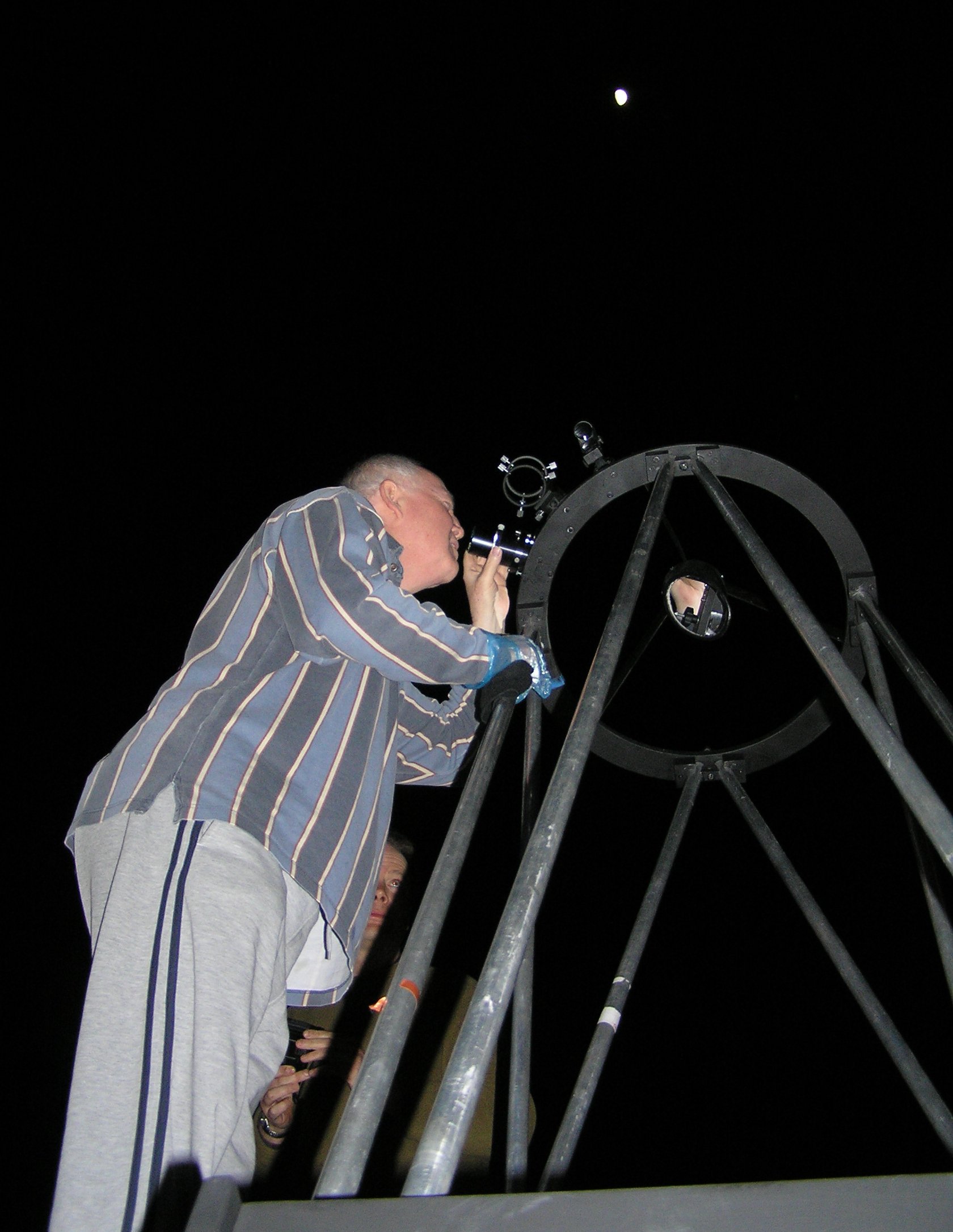 Fig 63. Paddy O'Sullivan observing the Moon with the Millennium Telescope. The Moon is visible at centre top.
 Fig 64. Image of the Moon taken at the eyepiece by a handheld digital camera (afocal coupling).
Assembly and disassembly of the telescope demonstrated at an Astronomy Workshop on 13 October 2013.
Almost two decades after first light... and the mirrors need to be resilvered. The MMT was dismantled, the mirrors removed for resilvering and, eventually, reassembled. Further details.
Why is the Millennium Telescope usually referred to as the MMT rather than the MT? Easy, MM is short for the year 2000, start of the second millennium!
Neil Morley & James Appleton