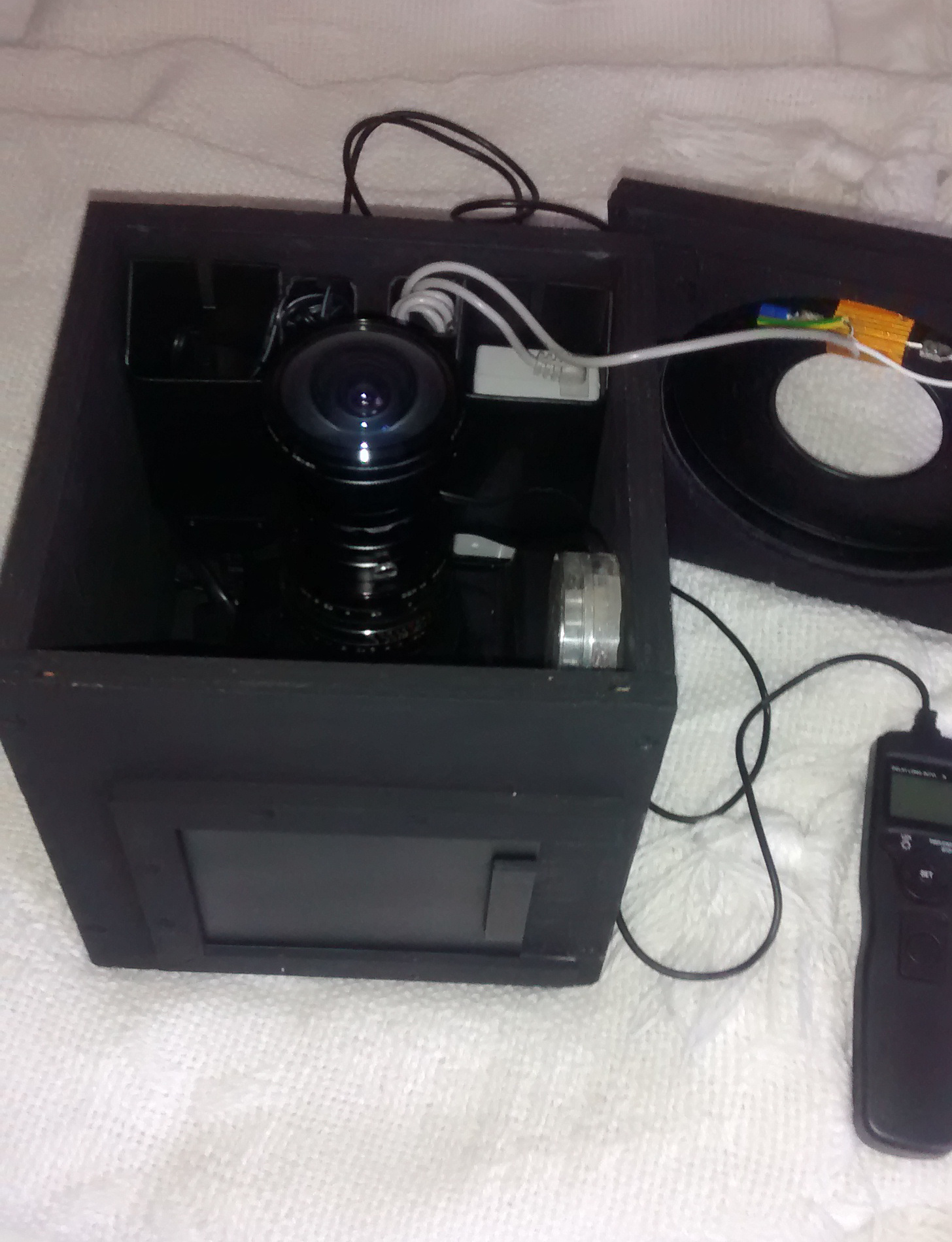
 The components inside the camera box, with the adapter-Helios-Spiratone lens combination.
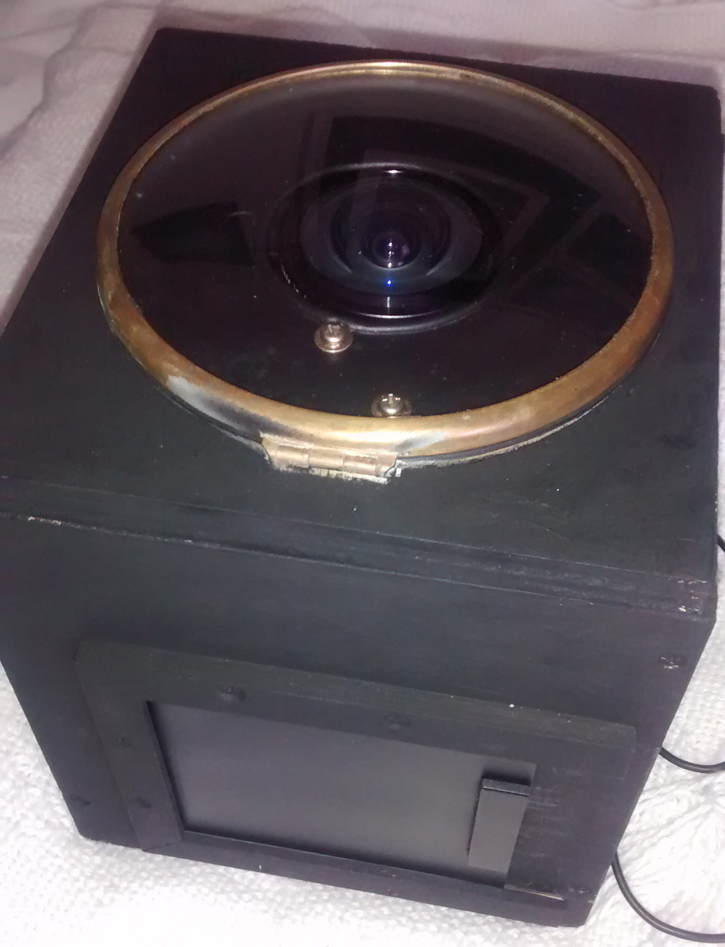 The box with the clock-glass cover shut, ready for use.
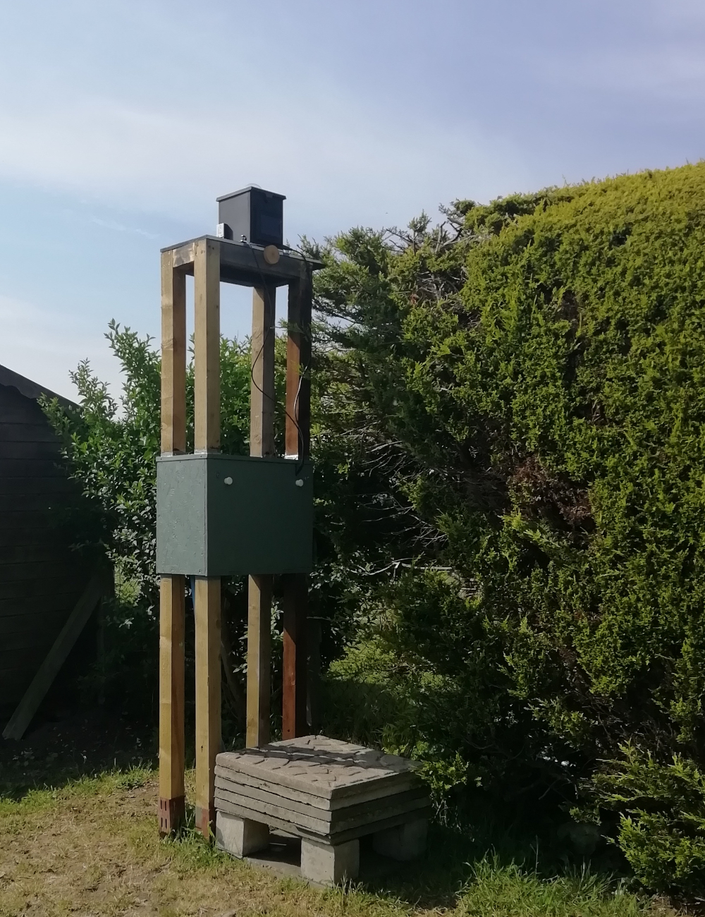 The tower with the box mounted on top.
Orwell Astronomical Society (Ipswich)
All-Sky Cameras
In 2018, Alan Smith started operating an all-sky camera. He was joined soon after by James Appleton and, in 2021, by Martin Richmond-Hardy. The cameras are described below. Images captured by the cameras.
Alan's first all-sky camera was a second-hand Canon 1100D, used with the following lenses:
The camera was originally mounted in a home-made wooden box which slotted into a mounting on the roof of a garden shed. The box was fitted with a 1.5 W dew heater resistor and a convex clock-glass to protect the lens. An intervalometer was used to take exposures of specified duration. Several improvements were made subsequently:
The components inside the camera box, with the adapter-Helios-Spiratone lens combination.
The box with the clock-glass cover shut, ready for use.
The tower with the box mounted on top.
The camera sensor was more electronically noisy than was desirable, resulting in numerous visible "sparkles" when images are examined at full resolution. Fortunately, the "sparkles" were easily distinguished from background stars as they appeared as points of light, whereas the stars exhibited trails due to the length of exposures used.
In order to measure the velocity of a meteor in a still image, an interrupter is necessary in the light path, between the lens and the camera sensor. The interrupter should interrupt the light between 10 and 16 times per second (recommendation of the DMS), resulting in a dashed line on the image, from which the velocity of the bolide can be estimated, and aiding differentiation between meteors and satellites. (Meteors, relatively fast-moving, display segmented trails whereas satellites, relatively slow moving, present unbroken trails.)
The 1970s-1980s camera used a set of rotating blades to interrupt the image. The modern form of interrupter is a liquid crystal (LC) shutter, comprising a sheet of twisted nematic LC material sandwiched between two sheets of crossed, polarising material. When the LC material is unpowered, its molecules are naturally twisted meaning that when used in conjunction with the crossed polarising sheets, the overall result is essentially transparent. If a suitable voltage is applied to the LC material, the molecules become untwisted and aligned to the electric field, and the shutter becomes opaque. By pulsing the drive voltage, the LC shutter can be made to interrupt light 10-16 times per second, suitable for use in estimating the velocity of meteors.
Initial experimentation with an LC in September 2018 was not totally successful, and the idea was not then pursued. However, in early 2020, Alan obtained a suitably sized (25 mm diameter) LC shutter from LC Tec, and was able to install it in a custom-made housing inserted in the camera between the mirror and the lens. In fact, there was just enough room, with a fraction of a millimetre to spare. In order to supply a pulsed voltage to the LC shutter, it had been necessary to remove the casing of the camera and drill two small holes in the internal framework to allow the passage of wires. This operation is not recommended on an expensive camera!
On 11 March 2020, after taking 251,483 images, the Canon 1100D finally, and not unexpectedly, failed with "error 20" (shutter/mirror failure). Alan had prepared for the eventuality, and had purchased a spare Canon 1100D, which he immediately pressed into service.
Alan was reluctant to drill holes in the framework of the replacement 1100D to enable installing the wires to the LC shutter until he had explored other options. One of the main considerations was the space available for fitting the LC shutter. The Sigma fisheye lens has to project an image onto the camera sensor at precisely 44 mm distance (in the case of a Canon DSLR): it is not possible to move the lens further from the camera and still focus on infinity. There were two options: purchase a mirror-less DSLR with a focus distance of around 20 mm (providing 24 mm of space to accommodate the LC shutter), or use a camera specifically designed for astronomical use.
Alan decided on the latter approach and purchased a ZWO ASI294mc camera. This has a "flange to sensor" distance of 6.5 mm meaning that an adapter to fit the Sigma lens would need to be a total of 37.5 mm in length, providing ample space to accommodate the LC shutter. At the time, no sensibly-priced commercial adapter was available so it was necessary to use an assembly of commercial and home made parts (see image below).
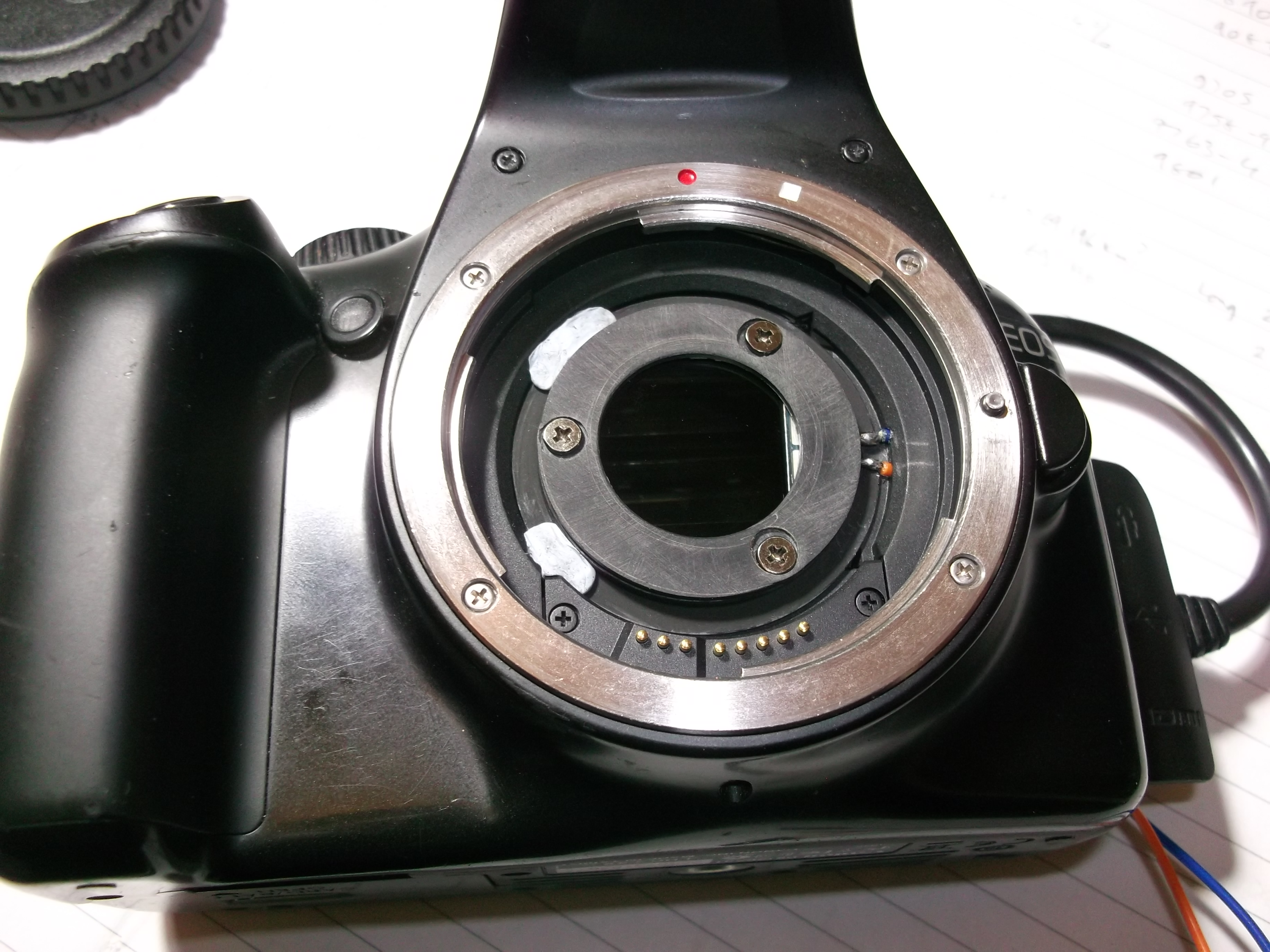
Initial tests of the camera were disappointing and images did not have anywhere near the expected quality. It turned out the ASI294 camera does not have an infra-red (IR) cut filter (it relies on an anti-reflection (AR) window in front of the sensor, held in place by a plastic ring and four screws). The lack of an IR cut filter caused major problems with focus (IR focuses at a different distance to visible light) and allowed terrestrially-generated IR (from e.g. domestic security lights) to flood the image causing many patches of purple coloured "clouds".
Alan was unable to source a 32 mm diameter IR cut filter (ZWO don’t make one!) and instead had to remove the AR window and install a 1¾" eyepiece IR cut filter in its place. This was not ideal as the 1¾" measurement includes the threaded bezel, with the filter itself having a diameter of only 25 mm. However, fortunately the arrangement worked well, allowing reasonable images to be captured once a suitable adapter was fabricated to allow the Sigma lens to be attached. The adapter was formed from a compound of T42-M42, M42-M42 and M42-EOS adapters.
 The LC shutter installed in the Canon 1100D. The lead out wires are at bottom right.
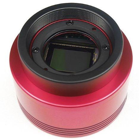 The AR window in the ASI294 is held in place above the sensor by a plastic ring and four screws.
 The compound adapter to mount the Sigma lens on the ASI294.
Once the camera was working satisfactorily, it was time to install it in a new, weather-proof housing. Alan fabricated the housing from an old plastic paint "tin", inverted, with an opening cut in the bottom (now at the top) fitted over a wooden frame. The opening was covered by a 100 mm diameter polypropylene dome, fitted into a modified plastic waste water fitting. The wooden frame contained a small 12v fan and electronic components. (In the image below, the fan and electrical connections are mounted between the base and the camera platform, and are not visible.) A small duct allowed the fan to force air upwards, past the lens into the dome. The enclosure was mounted on a sturdy aluminium base to hold it securely in place on the tower.
Once the new enclosure was proven to be satisfactory, it was time to fit the LC shutter. This was mounted just under the Canon bayonet lens fitting (M42-EOS adapter), with the lead out wires coming out through a hole in the home-made spacer (M42-M42 adapter).
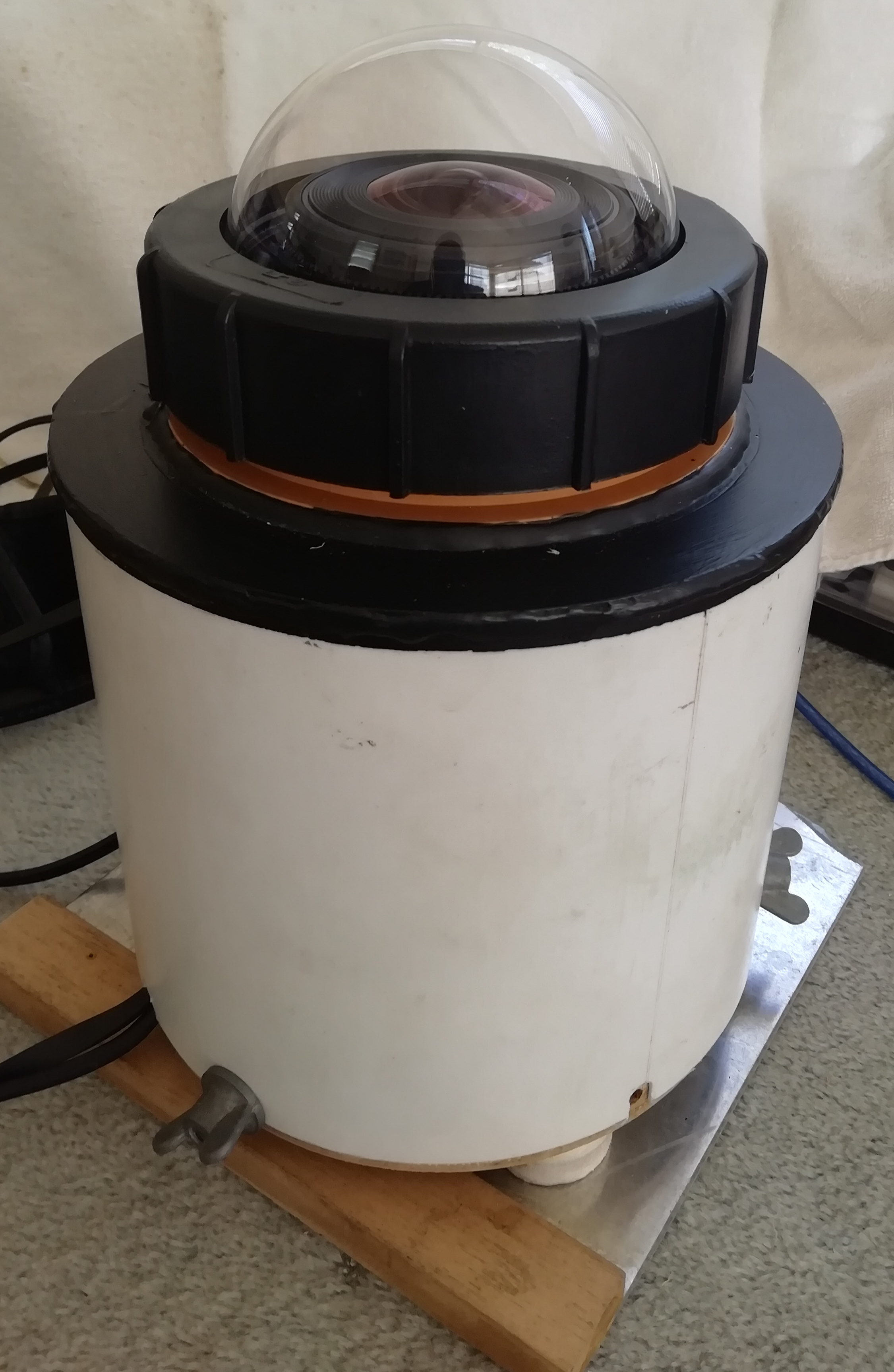 The enclosure, mounted on a sturdy aluminium base to hold it securely in place on the tower.
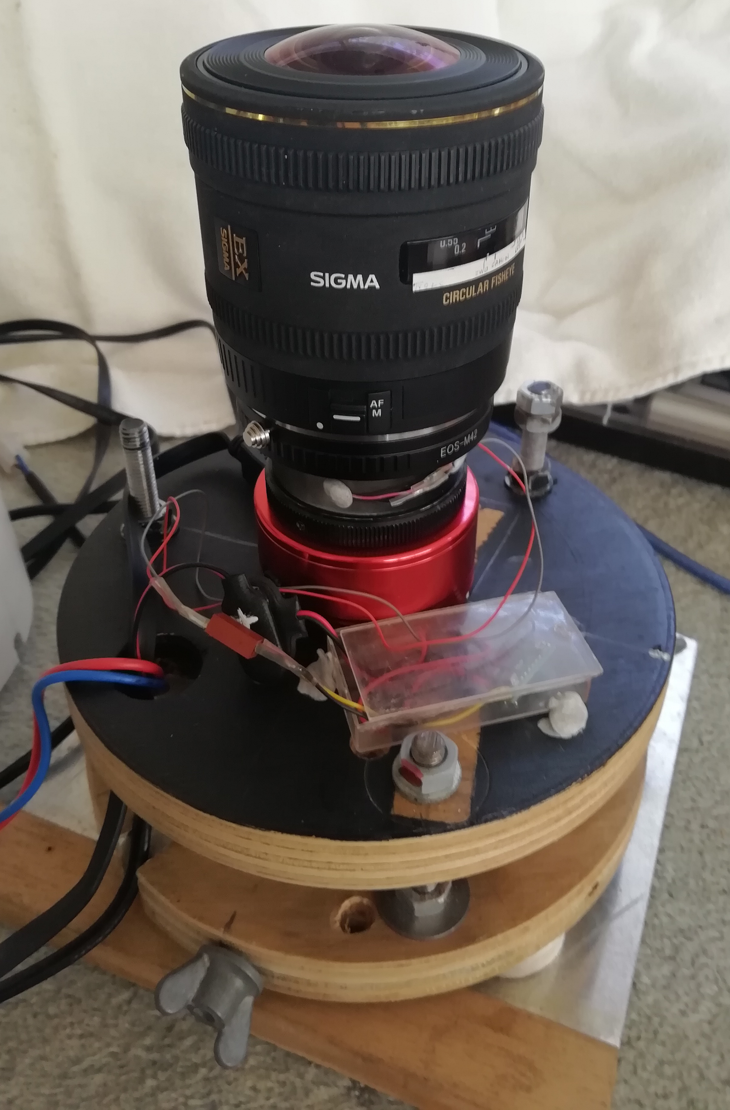 Inside the enclosure. Wires for the LC shutter can be seen coming from the spacer ring to the control electronics.
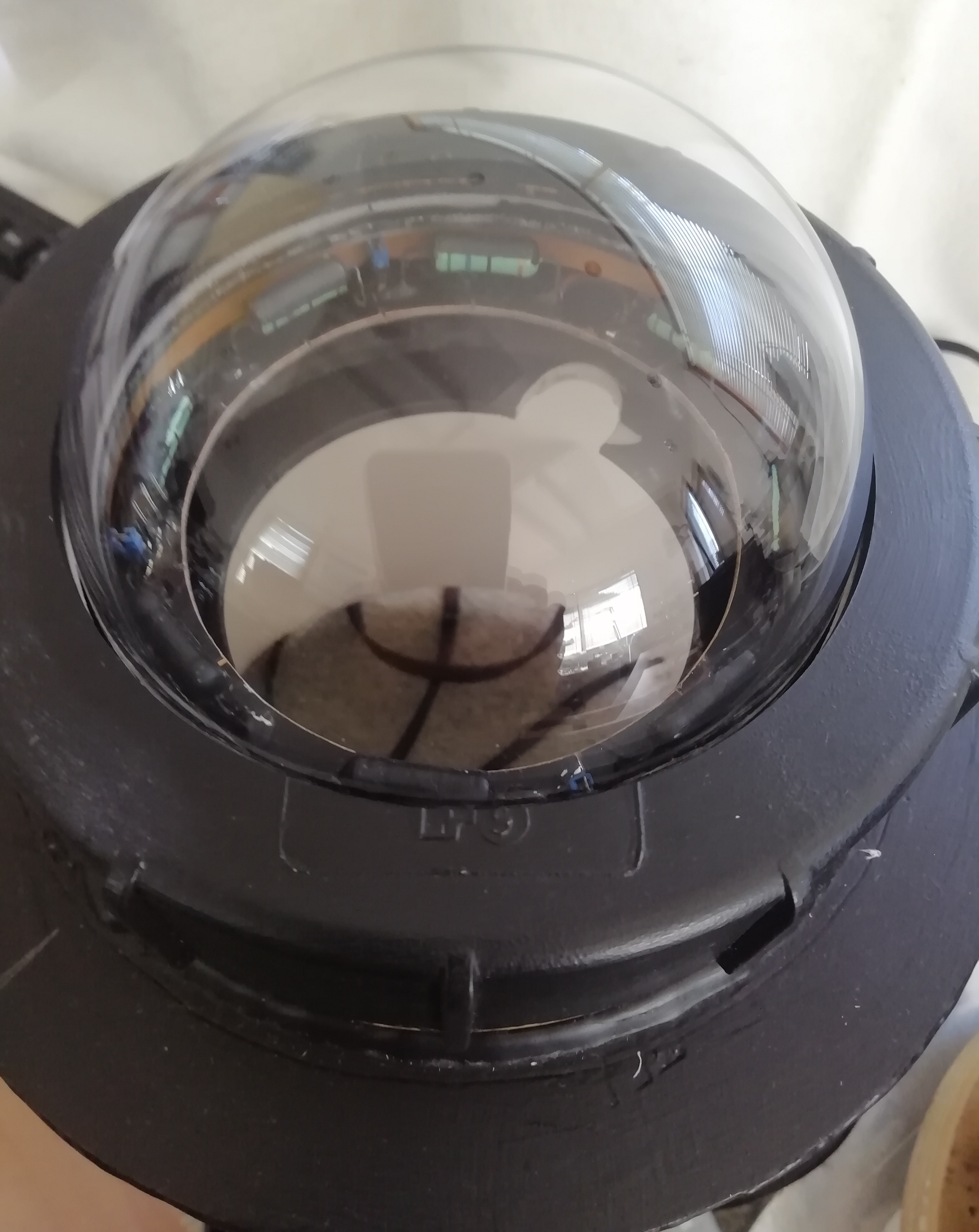 The dew heater is a circle of resistors mounted around the edge of the dome.
In use, another issue immediately raised its ugly head: at dusk and dawn the images showed interference patterns (similar to oil on water). The problem was not manifest when the sky was fully dark and was thought to be caused by the polarisation of sunlight (Rayleigh scatter) interacting with the polypropylene dome and LC shutter. The problem was easily cured by exchanging the polypropylene dome for an acrylic one!
Because the LC shutter uses polarised material as its outer surfaces, even with a voltage applied and nominally transparent, it causes considerable attenuation of light, exactly opposite to what is required by the astronomer! Additionally, the LC shutter alters the focal point of the lens to a considerable extent. (When the LC shutter was in use with the Canon 1100D, it altered the focal point such that the Sigma lens could still just rotate through its focus range to image at infinity, but another lens that Alan experimented with could not.)
Alan therefore decided to try an old fashioned approach, a mechanical interrupter in the form of a rotating shutter (similar to a propeller) in the light path. There was plenty of room beneath the lens (37.5 mm) so all(!) that was required was to source a suitable small motor, gearbox and shutter and mount them in the adapter. The motor/gearbox selected was 6 mm in diameter, 10 mm long. The shaft of the gearbox was of 1.95 mm diameter, an unusual size, which forced careful matching with the interrupter bore.
The shutter rotates at 8 revs/s and creates, with two arms, 16 breaks/s in the image. There is no loss of sensitivity (no attenuation when the shutter is open) and no change to the focal length of the optical train. Alan took special care to ensure that the shutter is as balanced as possible, and the arrangement creates no discernible vibration. Results so far are good, with an improvement in image quality over the LC shutter. However, it's not yet clear whether the ZWO or the Canon is better optically!
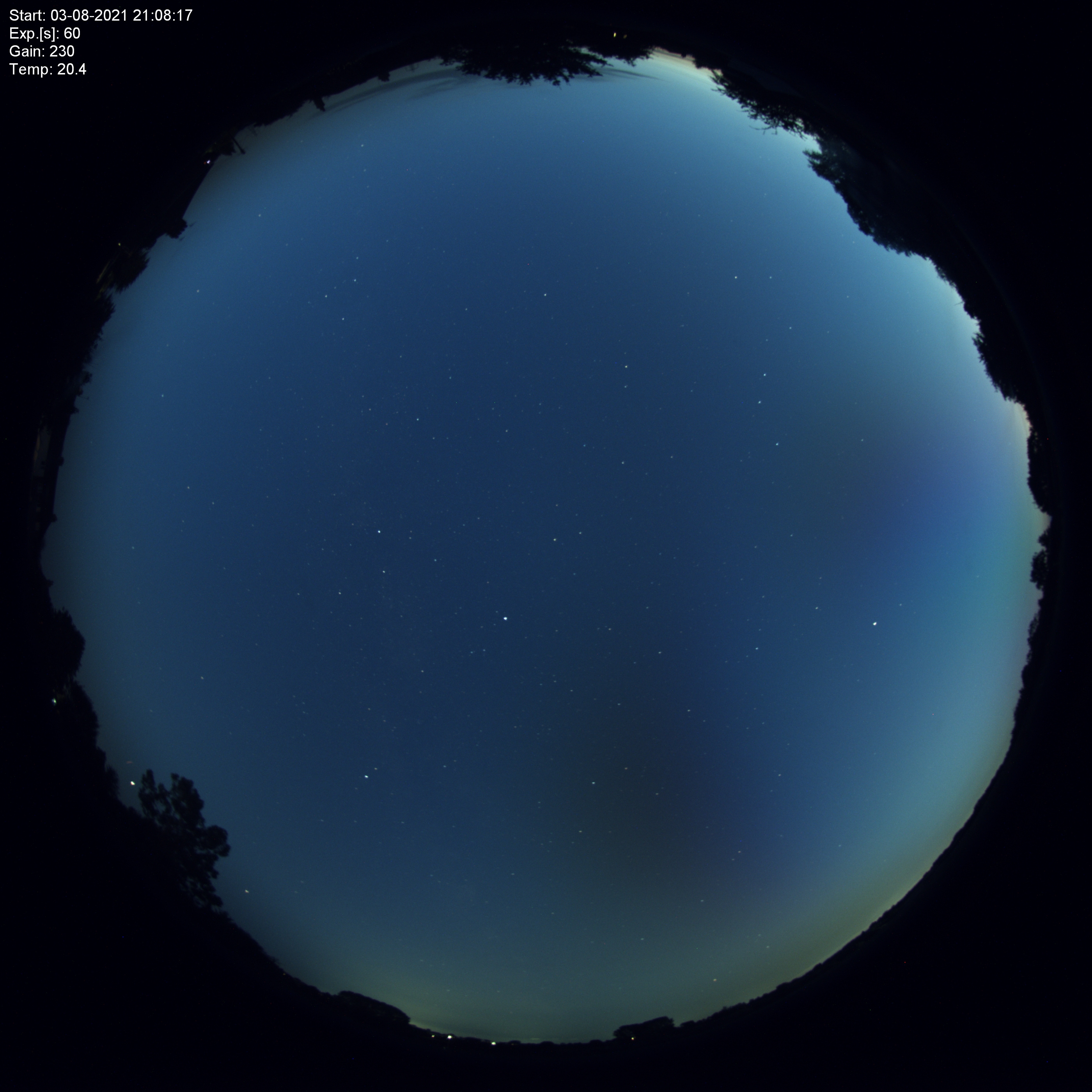 Interference patterns are visible at the bottom and RHS of the image.
 Components of the mechanical shutter.
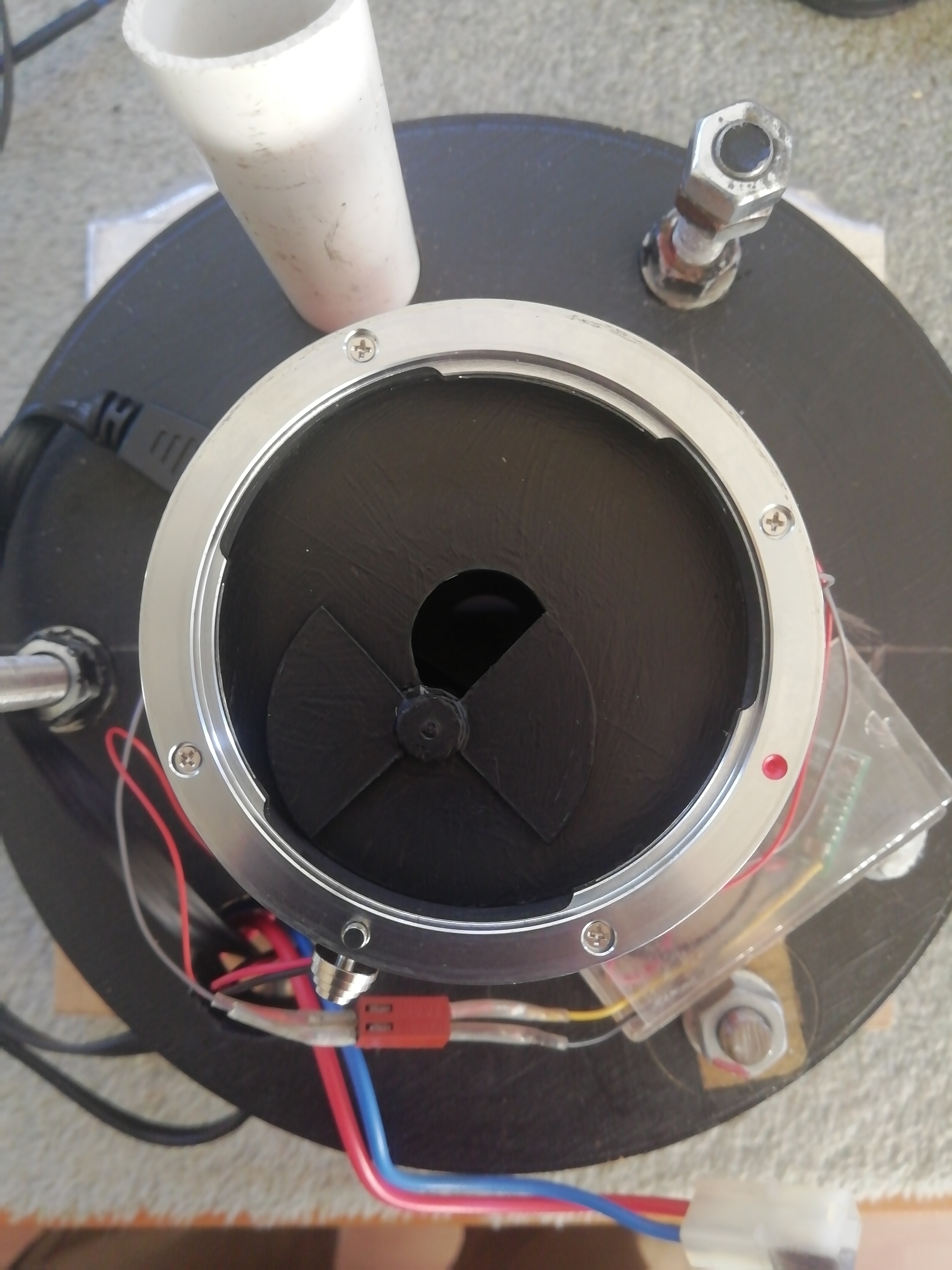 The mechanical shutter fitted.
James progressed through several iterations of all-sky imaging equipment as follows.
The first version, in use 10 June - 10 August 2018, comprised a Canon 6D MkII camera with 24-105 mm lens set to 24 mm. The camera was mounted on a fixed tripod and, by using short exposure times, generally 5 s or 8 s, star trailing was negligible. The camera took images every few seconds. The arrangement captured only a small fraction of the sky, and the aim was simply to explore what could be seen in wide-field views of the sky throughout the night.
The camera recorded many satellites and countless aircraft trails but, unfortunately, no meteors at all. It produced some interesting images but was too fragile and expensive to leave outside, unattended, all night.
The second version of equipment comprised a Raspberry Pi (RPi) single board computer (SBC) and PiCamera v2. This provided a serviceable albeit limited capability and, being relatively low cost, could be left out all night without worry! The RPi was mounted in a weatherproof ABS enclosure; the PiCamera protruded through a hole in the enclosure and was protected from the elements by a clear acrylic dome. The RPi was connected to the home network via an Ethernet cable (wi-fi proved unreliable). Four resistors, in two pairs positioned diametrically opposite inside the dome, delivered up to 6 W of heat to keep the dome free of dew. (Software control enabled adjustment of the power fed to the resistors.) At 62.2°x48.8°, the FoV was far less than "all sky", nevertheless, it proved sufficient to obtain some interesting results. The camera had a fixed focal ratio of f2.0, and was used with both exposure and ISO settings at maximum, respectively 10 s and ISO 800, which enabled detection of stars down to approximately magnitude 7.8 overhead, under ideal conditions. Although the PiCamera was set to record contiguous back-to-back images, in practice, processing times resulted in a short inter-image delay, causing visible gaps in some satellite trails. In use, the camera was positioned in the garden resting on a table, pointing vertically upwards, which resulted in images centred on the zenith. The images below show the inside of the enclosure and the equipment ready for use, awaiting nightfall. "First light" was on 04 October 2018.
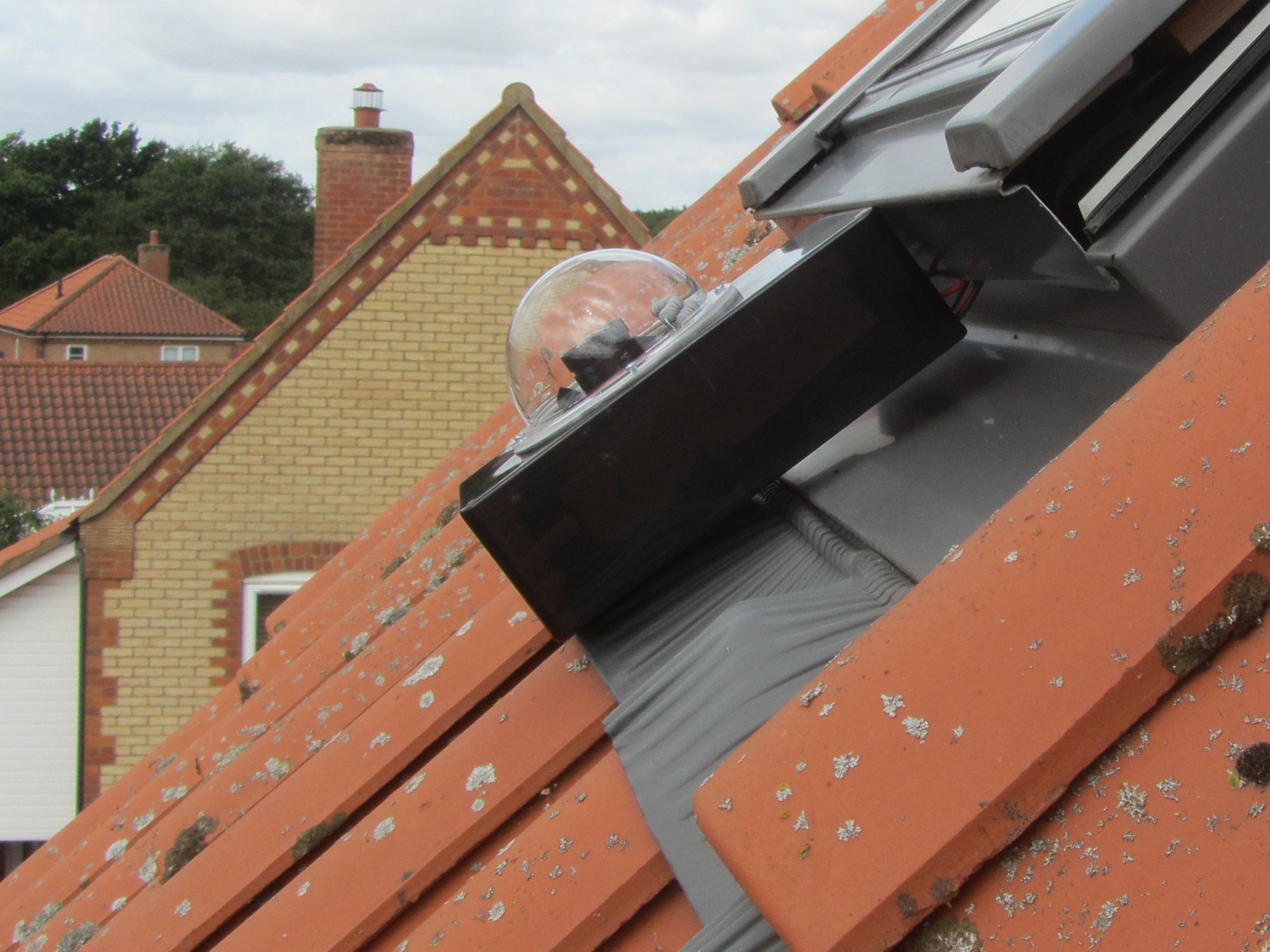
The small field of view of the PiCamera proved frustrating, and the third iteration of equipment was aimed at obtaining images of higher quality and with a wider field of view. To that end, the camera was upgraded to a ZWO ASI178MC with ZWO fisheye lens (2.5 mm, 1:1.2), operating under control of an RPi. In order to minimise the size of the enclosure housing the camera, a small acrylic dome was used. The dew heater system was similar to that of version 2, and utilised four resistors mounted inside the dome. However, because of the small size of the dome, they had to be mounted together, rather than being spread around the circumference. The equipment was initially operated under the INDI (Instrument Neutral Distributed Interface) software suite [1]. "First light" was on 29 June 2019. In use, the ASI178MC camera was positioned outside a window in the roof of the house, providing a good southern horizon but a severely restricted northern view (due to the roof itself). Surprisingly, positioning the camera in this way was repeatable.
Although INDI's camera control capabilities proved satisfactory, the software enabled production of images only in FITS (Flexible Image Transport System) format, and provided no support to convert files to alternative formats for post-processing. Frustration with the FITS format led to the replacement of INDI with software by Thomas Jacquin [2]. First light of the ASI178MC camera with Thomas Jacquin's software was on 12 July 2019.
At first, the software was used unmodified, as downloaded from github. However, throughout the use of version 4 and later, it was gradually tailored and optimised to support James's pattern of use of the camera. Ultimately, the software was completely re-factored.
The ZWO camera and fisheye lens imaged several bright meteors and generally performed satisfactorily. However, the lens was of low quality, and suffered from considerable distortion at the edges of the FoV which made it difficult to triangulate the paths of some meteors. As a fifth iteration of equipment, the lens was replaced with a Fujinon fish-eye lens, model CF2.7HA-L1, 1:1.8, 2.7 mm (obtained pre-owned from ENS Optical). The 5th iteration came into use on 28 July 2020.
On decommissioning version 4, it was apparent that mounting the dew heater resistors close together had been a serious mistake. The circulation of warm air inside the dome appeared to be limited, and it had been necessary in winter to run the resistors at a total power of 3.0 W to ensure that the entire dome was sufficiently heated to prevent dew from forming; at this power, the resistors were too hot to touch, and in fact had caused charring of the ABS in the vicinity. Fortunately, the Fujinon lens introduced in version 5 was considerably larger than its predecessor, necessitating a larger acrylic dome (10 cm diameter versus 8.5 cm) and a new, larger enclosure. The larger dome enabled the fitting of eight dew heater resistors equally spaced around the circumference, providing an even distribution of heat. Even though the volume of air inside the dome of version 5 was considerably larger than that of versions 3 and 4, because of the greater number of resistors and the more even distribution of heat, each resistor could be run at lower power, in use never more than warm to the touch, with no danger of causing charring of the enclosure.
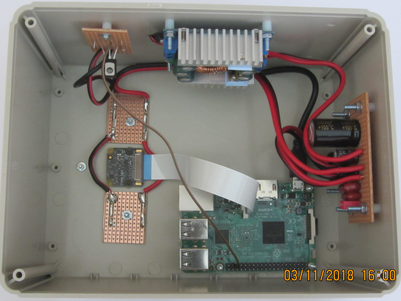 The inside of the enclosure showing the Pi, PiCamera, power supply and associated components.
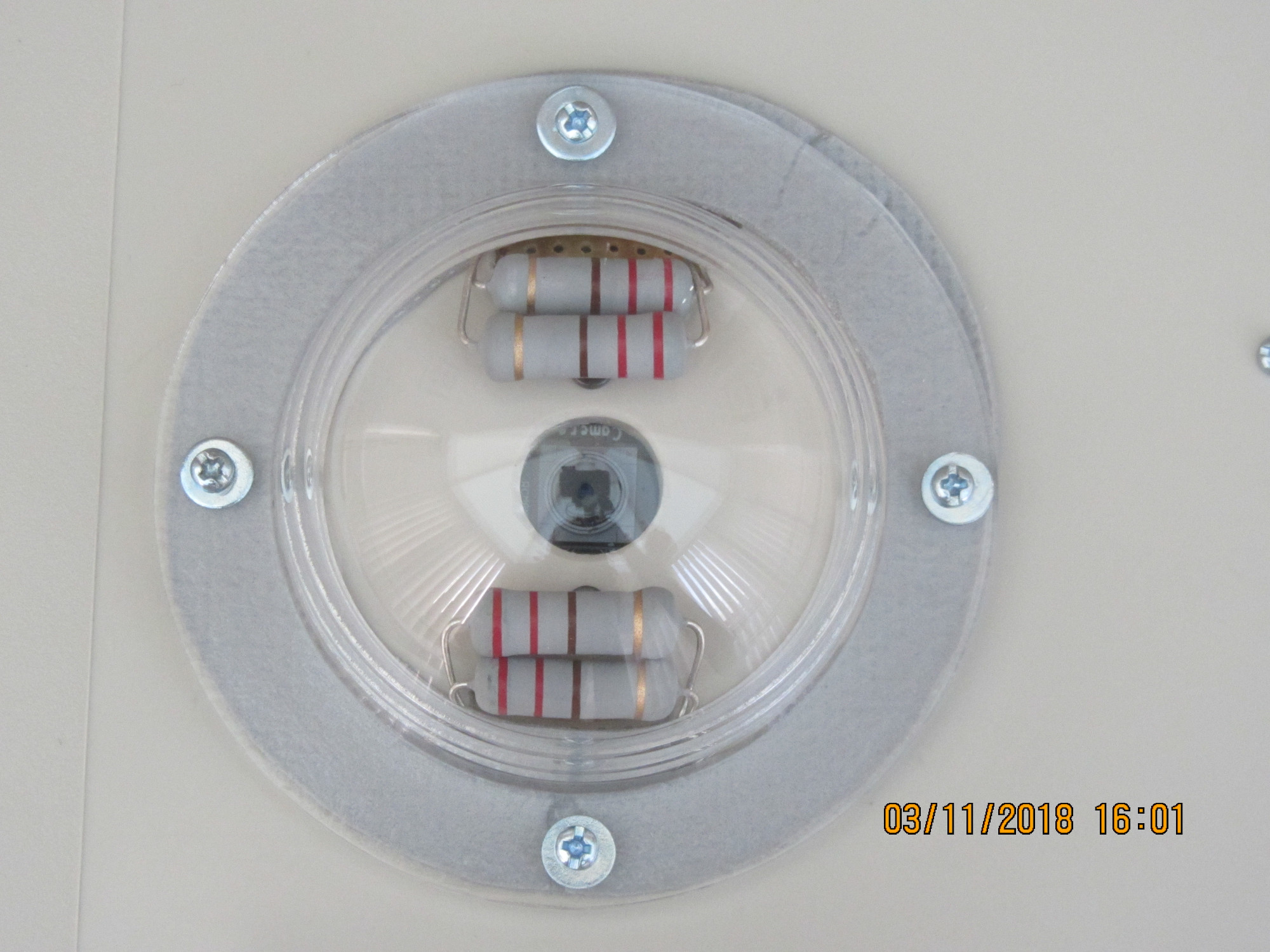 The lens of the PiCamera and dew heaters inside the acrylic dome.
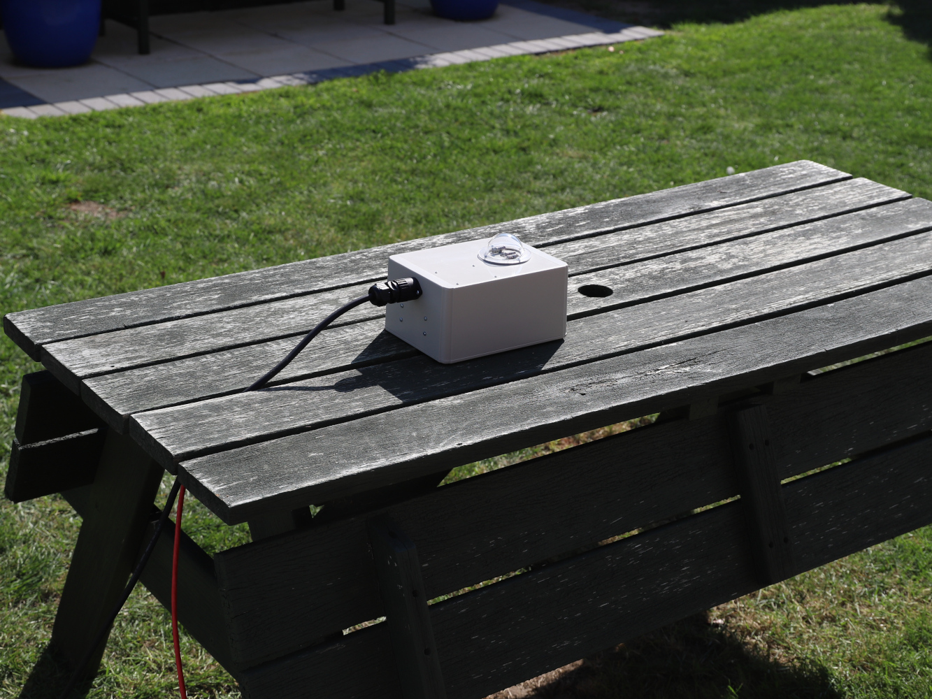 The PiCamera ready for use, awaiting nightfall.
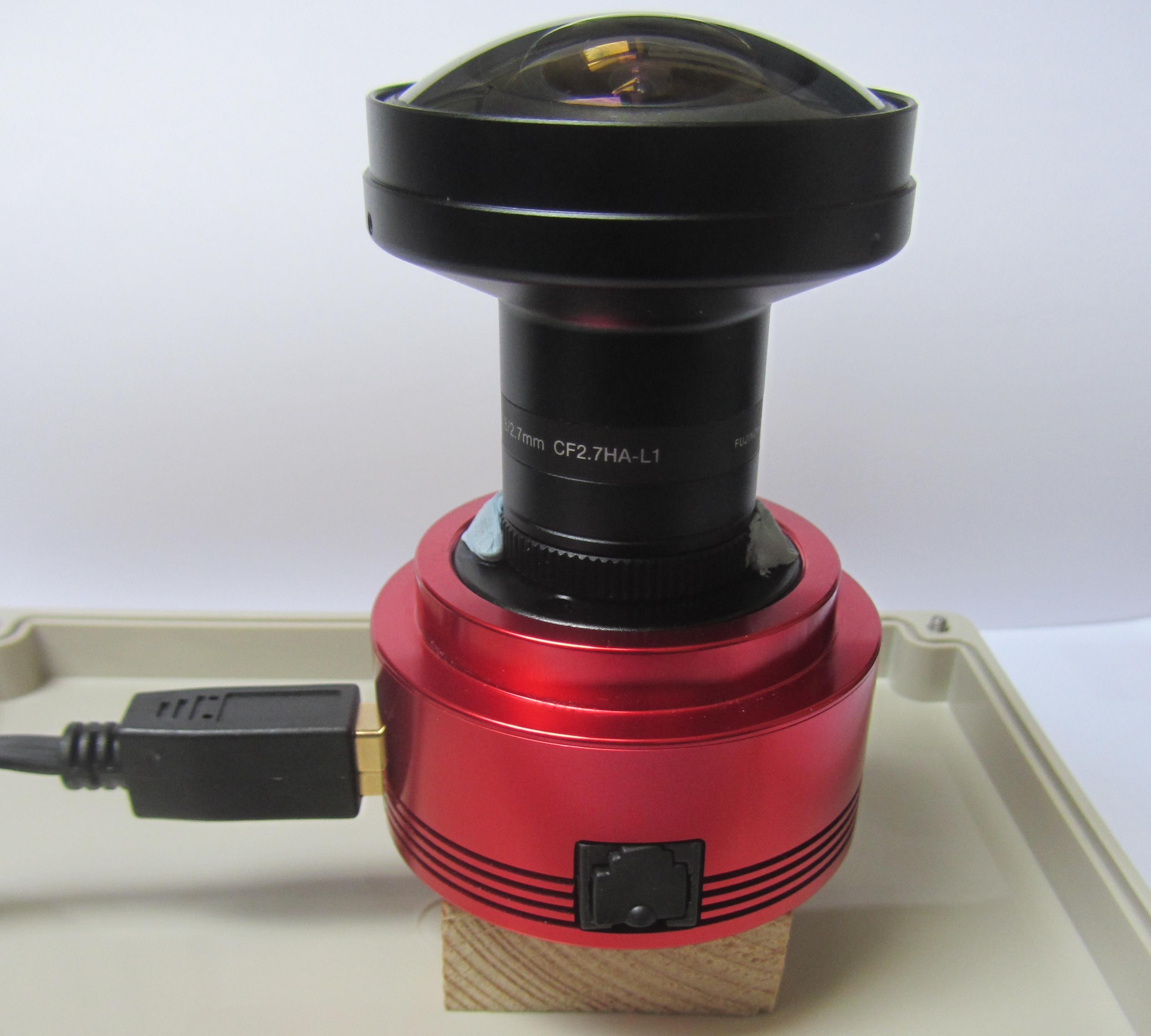 The ASI camera and Fujinon lens.
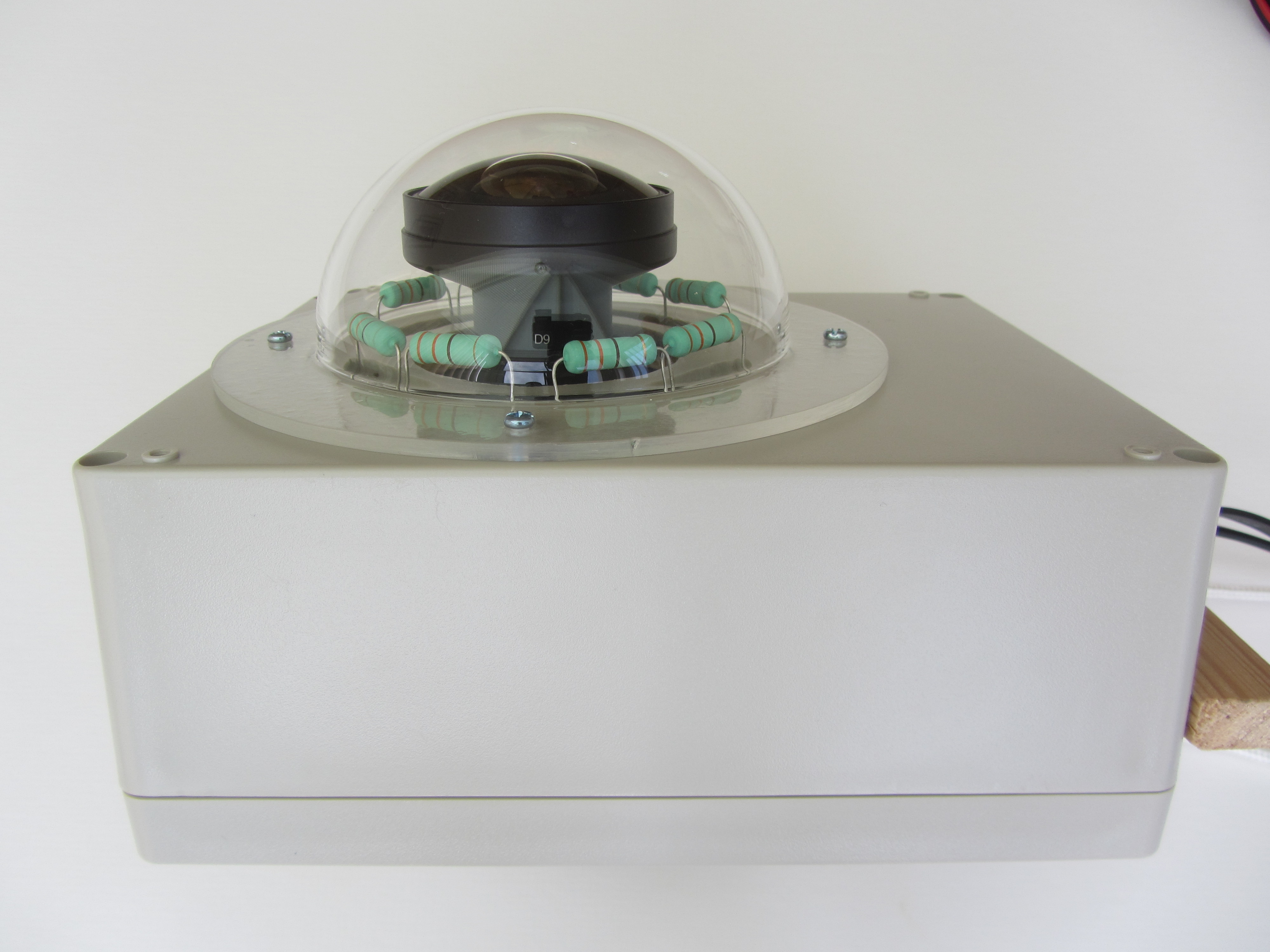 The Fujinon lens and dewheaters.
 The ZWO camera ready for use, awaiting nightfall.
See the description in the June 2021 Newsletter, pp. 22-25.
[1]
Open Astronomy Instrumentation, "Discover INDI", www.indilib.org/about/discover-indi.html.
[2]
Thomas Jacquin, "A Raspberry Pi operated wireless allsky camera", github.com/thomasjacquin/allsky.git.
James Appleton, Alan Smith